
Manual

3
IM 77J08A05-01E 1st Edition 2008.01.15-00
3. EXTERNAL WIRING
WARNING
Be sure to turn OFF the power supply before wiring to
avoid the risk of electric shock. Use a tester or similar
device to ensure that no power is being supplied to a
cable to be connected
.
M4 screw terminals are provided for the connection of external
signals. Attach a crimp-on lug to each wire for connection to the
terminals.
●Recommended cables: A nominal cross-sectional area of 0.5
mm2 or thicker for signal cables, and that of 1.25 mm2 or thicker
for power cables.
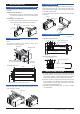
Wiring Diagram
1
2 3
4 5
6 7
6
7
4
5
+
-
Output
Power Supply
+
-
1
2
PS+
–
-
2
3
+
+
-
–
COM
• Using External
Power Supply
Input
• Using Internal Power Supply
NOTE
●Do not connect anything to the terminals that are not
used in the wiring diagram. Otherwise it may cause
the malfunction or damage.
●The power line and input/output signal lines should
be installed away from noise-generating sources.
Otherwise accuracy cannot be guaranteed.
●Adhere strictly to the specications to avoid
overheating or damage. Before turning on the power,
ensure the following:
(a) Power supply voltage and input signal value
applied to the product should meet the required
specications.
(b) The external wiring to the terminals are as
specications.
●Do not operate the product in the presence of
ammable or explosive gases or vapors.
●The product is sensitive to static electricity; exercise
care in handling. Before you operate the product,
touch a nearby metal part to discharge static
electricity.
Power Supply and Isolation
Power supply voltage: 24 V DC ±10% (percentage ripple: less
than 5% p-p)
Current consumption: FA5A 100 mA, FA5V 90 mA
Insulation resistance: 100 MΩ at 500 V DC between input and
output, output and power supply, and input and
power supply.
Withstand voltage: 1500 V AC/min. between input and (output
and power supply)
500 V AC/min. between output and power supply.
4. SETTING PARAMETERS
The parameters are set as you specied in your order. Refer
to the following to change the default settings.
Set the parameters using a PC (VJ77 Parameter Setting Tool)
or the Handy Terminal. Refer to "5. List of Parameters" in this
manual and the User’s Manual for VJ77 PC-based Parameters
Setting Tool (IM 77J01J77-01E) or the User’s Manual for JHT200
Handy Terminal (IM JF81-02E). Parameters are shown in
brackets "[ ]".
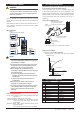
Connection of Setting Tools
VJ77 Dedicated adapter
[Provided with VJ77]
PC with VJ77 installed
Dedicated cable
[Provided with VJ77]
*Be sure to use the VJ77 of version R1.05 or later.
JHT200
Handy Terminal
JUXTA communication cable
3 pin connector (F9182ED)
[Provided with VJ77 and JHT200]
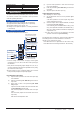
Setting Low Cut Point
Set the low cut point in [B07: LOW CUT].
Setting range: 0.3 to 100% of the input range (setting
resolution 0.1%)
Output=Input
Low cut point
Input
Hysteresis
(fixed at approx. 0.2%)
Output
5. LIST OF PARAMETERS
Parameter Display Items
A DISPLAY Display
A01 INPUT Input value
A02 OUTPUT Output value
A03 STATUS Status (*1)
A04 REV NO Revision number
B SET Setting
B01 TAG NO.1 Tag number 1
B02 TAG NO.2 Tag number 2
B03 COMMENT1 Comment 1
B04 COMMENT2 Comment 2
B07 LOW CUT Low cut point
C ADJUST Adjustment
C01 OUT 0% Output 0% adjustment