
Manual

38
IM 12D06D05-01E
6-2. Cell constant manual
The intention of this calibration routine is to fine
tune a sensor for which only the nominal cell
constant is known, or recalibrate a sensor that
has been changed (or damaged) in the course
of operation. Choose 1st or 2nd compensation
to suit the calibration solution used. The solu-
tion should be prepared or purchased, meeting
the highest standards of precision available.
Allow the sensor to reach stable readings for
both temperature and conductivity before ad-
justing to correspond to the calibration solution
value. The setting of a cell constant for a new
(replacement) sensor is also possible in this
routine. This avoids the need for entry into the
commissioning mode, which may have another
authorization (password) level.
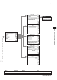
Press the keyandchoose“
Execute: Cali-
bration.
” Press “
Cell constant (manual)
” to
execute calibration.
6-3. Cell constant automatic
This routine is built around the test method
describedinOIML(OrganisationInternationale
de Metrologie Legale). International Recom-
mendation No. 56. It allows the direct use of
the solutions prescribed in the test method, au-
tomatically selecting the appropriate tempera-
ture compensation. The look up table is used
to find the appropriate conductivity reading for
themeasuredtemperature.Seeappendix3for
OIMLsolutions
Press the keyandchoose“
Execute: Cali-
bration.
”Press“
Cell constant (automatic)
”to
execute calibration.
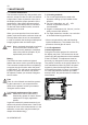
6-4. Air (zero) calibration
With the clean dry cell in open air, the reading
should be zero. The Air cal compensates for
excess cable capacitance, and gives a better
accuracy at low readings. This should be done
for all installations during commissioning. After
some time in service a dirty sensor may well
show a high zero offset because of fouling.
Clean the sensor and try again.
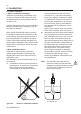
•Waitforthesensortodry(becauseaircal
must be made with no current flow in the
sensor, that is, the sensor must be dried
while being exposed to air).
•Thesensormustbeinstalledinan
environment free of electromagnetic
interference and radio frequency
interference.
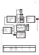
Press the keyandchoose“
Execute: Cali-
bration.
”Press“
Air calibration
”toexecuteit.
CAUTION
The temperature compensation should be set
to NaCl when confirming zero during air calibra-
tion.
6-5. Sample calibration
With the sensor in situ, a sample can be taken
for laboratory analysis. Sample calibration
records the time and reading, and holds these
in memory until the analysis has been com-
pleted. The laboratory data can then be entered
regardless of the current process value, without
the need for calculations.
Press the keyandchoose“
Execute: Cali-
bration.
” Press “
Sample
” to execute sample
calibration.
Press [
Take Sample
] to record a collected
samplevalueinmemory.Re-entertheSample
Cal. screen and press [
Start calibration
] to
perform a sample calibration. This updates the
recorded data.
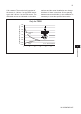
6-6. Temperature coefficient calibration
Simply input the solution conductivity at the
reference temperature (T
R
) after allowing the
sensor to stabilize at elevated temperatures.
The ISC450G will calculate the temperature
coefficient for you. The ideal temperature for
this calibration is the normal process value (T
P
).
This calibration is enabled if the Temperature
Compensationissetto“TC.”
Press the keyandchoose“
Execute: Cali-
bration.
” Press “
Temperature coefficient
” to
execute this calibration