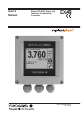
User’s Manual Model ISC450G [Style: S2] Inductive Conductivity Converter IM 12D06D05-01E 4th Edition
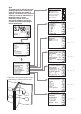
Note This page may be referred to when reading pages where subsequent submenu screens are shown in the text. Connection to the relevant submenu screen is indicated by a doted line with an arrow. Note that screens in the text are typical examples and actual screens may differ depending on the set parameters. Commissioning Connection to the relevant submenu screen is indicated by a doted line with an arrow. Measurement setup Measure Conductivity only Configure sensor Temperature settings Temp.
PREFACE Electrostatic discharge The EXAxt converter contains devices that can be damaged by electrostatic discharge. When servicing this equipment, please observe proper procedures to prevent such damage. Replacement components should be shipped in conductive packaging. Repair work should be done at grounded workstations using grounded soldering irons and wrist straps to avoid electrostatic discharge.
ii The following safety symbols are used on the product as well as in this manual. DANGER This symbol indicates that an operator must follow the instructions laid out in this manual in order to avoid the risks, for the human body, of injury, electric shock, or fatalities. The manual describes what special care the operator must take to avoid such risks.
iii TABLE OF CONTENTS PREFACE 1. INTRODUCTION AND GENERAL DESCRIPTION......................................................1 1-1. Instrument check....................................................................................................1 1-2. Application..............................................................................................................1 2. GENERAL SPECIFICATIONS OF EXAxt ISC450G.....................................................2 3. INSTALLATION AND WIRING.............
iv 4. OPERATION OF EXAxt ISC450G..............................................................................16 4-1. Main display functions..........................................................................................16 4-2. Trending graphics.................................................................................................16 4-3. Zoom in on details................................................................................................16 4-3-1. Actual mA1..................
v 6. CALIBRATION............................................................................................................36 6-1. Before calibration.................................................................................................36 6-2. Cell constant manual............................................................................................38 6-3. Cell constant automatic........................................................................................38 6-4.
vi
1 The Yokogawa EXAxt ISC450G is a converter designed for industrial process monitoring, measurement and control applications. This instruction manual contains the information needed to install, set up, operate and maintain the unit correctly. This manual also includes a basic troubleshooting guide to answer typical user questions. Yokogawa can not be responsible for the performance of the EXAxt converter if these instructions are not followed. 1-1.
2 2. GENERAL SPECIFICATIONS OF EXAxt ISC450G A) Input specifications : Compatible with the Yokogawa inductive conductivity ISC40 series with integrated temperature sensor: NTC30k or Pt1000 B) Input range Conductivity Minimum Maximum Temperature Cable length : : : : : 0 to 1999 mS/cm at 25 °C (77 °F) reference temperature 1 µS/cm (at process temperature) 2 S/cm (at process temperature) -20 to +140 ºC (0 to 280 ºF) max.
3 Hold : Contact can be used to signal the HOLD situation. Fail safe : Contact S4 is programmed as fail-safe contact. (*)Note: When contact output current is more than 4 Amps, ambient temperature should be less than 40 ºC. Contact closed : Remote range switching to 10 times the programmed range. : If impedance > 100 kΩ: "Range1, 2" (“Programmed range for mA1 and mA2 output" is "Range1, 2.
4 N) Safety and EMC conforming standards , Safety : EN 61010-1 CSA C22.2 No.61010-1 UL 61010-1 FM3611 Class I, Div.
5 3. INSTALLATION AND WIRING The ambient temperature and humidity of the installation environment must be within the limits of the instrument specifications. (See chapter 2). 3-1-2. Mounting methods Refer to figures 3-2 and 3-3.
6 Unit: mm (inch) +1 138 0 (5.43") min.195(7.75") min.185 (7.25") +1 138 0 (5.43") 138(5.43") M6 138 (5.43") M5 M6 Figure 3-2. Option /PM: panel mounting diagram (Note) When option code "/UM" is specified, universal pipe/wall/pannel mounting kit are supplied--same as option code "/U" and "/PM" both specified. wall mounting 13 (0.51") 80 (3.15") pipe mounting (vertical) pipe mounting (horizontal) 2x Ф6.5 (0.26") 200 (7.87") 4x Ф10 (0.4") 35 (1.38") 15 (0.6") 70 (2.75") 154.5 (6.
WARNING This connector for software must be used only by 7 Yokogawa’s servicefor personnel. connector (future) software input terminal block potentiomerter LCD bracket protective shield bracket 6 X M20 glands Note: ISC450G-A(D)-U The enclosure is provided with stoppers in stead of M20 cable glands for the unused holes. These stoppers must be removed and replaced by FM approved conduit fittings in accordance with good installation practice. See APPENDIX 6, Control drawing for FM approval. Figure 3-4.
8 3-2-2. Cables, Terminals, glands and conduit adapter ISC450G-A(D)-A The ISC450 is supplied with terminals suitable for the connection of finished wires in the size range of 0.13 to 2.5 sq.mm. (26 to 14 AWG). The cable glands supplied will form a tight seal on cables with an outside diameter of 6 to 12 mm (0.24 to 0.47 inches). Unused cable entry holes must be sealed with cable glands including the blind plugs supplied.
9 Adapter for conduit work When protect the cable with a conduit, replace the M20 cable gland with a cable gland of optional conduit adapter, and set the adapter shown as Figure 3-5c. Unit: mm(inch) Nut Packing G1/2 screw (/AFTG), 1/2 NPT screw (/ANSI) M20 screw (/AM20) Adapter Figure 3-5c. Conduit adapter FRONT GLANDS REAR GLANDS Sensor mA1 HART Power output signals Contact output S1 S2 Contact output mA2 S3 S4 Contact input Figure 3-6. System configuration 3-3.
10 WARNING Fuse replacement should be performed only by a qualified service person. See Sec.7. MAINTENANCE, Fuse. Fuse ratings: Power supply Fuse type 12-24VDC, 10W max 2A/250V, Slow 100-240VAC, 15VA max 0.5A/250V, Slow 3-3-2. Access to terminal and cable entry Terminals 1 and 2 are used for the power supply. Guide the power cables through the gland closed to the power supply terminals. The terminals will accept wires of 2.5 mm2 (14 AWG). Always use cable finishings if possible. 3-3-3.
11 (M4 screw) N 1 L POWER 100-240 VAC/15 VA/ 50/60Hz FUSE: 500 mA/250 VAC/T AC (M4 screw) Figure 3-8-a. External grounding 3-4. Wiring the contact signals 3-4-1. General precautions The contact output signals consist of voltage-free relay contacts for switching electrical appliances (SPDT). They can also be used as digital outputs to signal processing equipment (such as a controller or PLC).
12 It is necessary to use screening/shielding on the output signal cables. Terminal 63 is used to connect the shielding. 3-6. Wiring the sensor 3-6-1. General precautions The sensor cable transmits low voltage, high frequency signals and should be installed separately from any high voltage, high current and/or power switching cables. This is to avoid any unintentional cross talk or other kind of interference of the conductivity measurement. 3-6-2. Connecting the sensor cable to the converter 1.
13 DIMENSIONS 11 12 17 13 15 16 14 L= 5000 ( 200 ) thermistor INSTALLATION INSTRUCTIONS BULK-HEAD MOUNTING secondary primary UNIT: mm (inch) ground 40 (1.57) G3/4 wrench opening 20 ( 0.79 ) wrench opening 32 ( 1.42 ) Ø 40 ( 1.57) 100 (3.94) ca 240 (9.45) YOKOGAWA t I D d d = distance min 25 mm (1") D = acces port size min 48 mm (1.89") distance min. 25 mm (1) access port side min 48 mm (1.89) 47(1.85) Figure 3-9b. Dimensions 3-6-4.
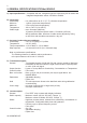
14 14 14 17 13 12 11 11 12 13 17 15 16 16 15 WF10 14 14 BA10 EXA TRANSMITTER / CONVERTER 15 Core 16 Screen White Co-axial cable 14 Overall Screen 13 Core 17 Screen Brown Co-axial Cable 11 Red 12 Blue 11 11 12 12 13 13 14 14 15 15 16 16 17 17 12 (blue) 14 (overall screen) Co-axial cable (white) 13 (core) 15 (core) 17 (screen) 16 (screen) Co-axial cable (brown) 11 (red) Figure 3-10.
15 3 INSTALLATION AND WIRING Figure 3-11.a. Figure 3-11.b. Figure 3-11.c.
16 4. OPERATION OF EXAxt ISC450G 4-1. Main display functions Tag:EXAxt ISC450 3.760 25.0 16.64 Go to trend screen + mS/cm Go to zoom screen 4-3. Zoom in on details This button gives access to the diagnostic information of the analyzer. The following messages will appear under normal (default) conditions: Go to status screen - Home key back to mainscreen. - One level up. Go to maintenance screen Figure 4-1.
17 4-3-1. Actual mA1 = the current output in mA of the first current output, which is defined as mA1. The range and function of this mA output can be set in: Routing: Commissioning >> Output setup >> mA1 4-3-4. C.C. (factory) = the nominal cell constant as determined by the factory calibration during production. This value is set during commissioning, and is found on the nameplate of the sensor or the calibration certificate. Routing: Commissioning >> Measurement setup >> Configure sensor 4-3-5. C.C.
18 4-3-14. HART Device revision Sometimes the firmware of a device is updated in a way that the communication file (HART DD) need revision too. In this case the revision level is increased by one. The revision level of the HART DD must match the revision level of the Firmware. The revision level is expressed by the first two characters of the filename. The following files should be used when the HART Device revision level is 2. (0201.aot, 0201.fms, 0201.imp, 0201.sym) 4-3-15.
19 4-7.
20 5.MENU STRUCTURE COMMISSIONING 5-1. Configure sensor Measuring unit /cm /m Either /cm or /m can be chosen here. The Process values will be expressed in S/cm or S/m respectively. Cell constant (factory) Cell constant given by factory calibration. Usually given on a label on the sensor or the calibration certificate. Measure Process values to be measured can be selected to suit the user’s preference.: Conductivity only, Concentration only or one of both Conductivity and Concentration. 5-2.
21 Measurement setup Measure Conductivity only Configure sensor Temperature settings Temp. Compensation Calibration settings Concentration Enter 5 MENU STRUCTURE COMMISSIONING Menu Parameter Default Range values min. max. Configure Sensor Temp. Comp. Manual Comp. Temp. Coef Temp. Coef 1.88 cm-1 25ºC, 77ºF 25ºC, 77ºF 2.10%/ºC 2.10%/ºC 50.0 cm-1 100ºC, 211ºF 139ºC, 284ºF 3.5%/ºC, 2.0%/ºF 3.5%/ºC, 2.0%/ºF Cell constant Reference Temp. Manual Temp. T.C.methods 1 T.C.methods 2 0.
22 5-4. Calibration settings Air adjust limit To avoid cable influences on the measurement, a “zero” calibration with a dry sensor may be done. If a connection box (BA10) and extension cable (WF10) are being used, “zero” calibration should be done including this connection equipment. As the calibration is performed in air the resistivity is infinite (open connection). Higher conductivity values than the air adjust limit indicate the cell is not in air or is still wet.
23 Measurement setup Measure Conductivity only Configure sensor Temperature settings Temp. Compensation Calibration settings Concentration Enter Concentration measurement is only possible if “measure” in the “Configure sensor” menu is set to “conductivity + concentration” or “Concentration only”. 5 MENU STRUCTURE COMMISSIONING Menu Parameter Calibration Air adjust c.c. high c.c. low Stabilization time Calib. interval Concentr. Table Table Default Range values min. 100.
24 5-6. mA output setup The general procedure is to first define the function (control, output, simulate, off) of the output and second the process parameter associated to the output. Available process parameters depend on selected “sensor type” and “measurement setup”. Off : When an output is set off the output is not used and will give an output of 4 mA. Control : A selection of P- PI- or PID control Manual : Static output required to maintain reset equilibrium state with setpoint.
25 5 MENU STRUCTURE COMMISSIONING mA2 similar structure to mA1 Menu Parameter Default Range values min. max. mA1 (output) Damping time 0.0 sec. 0.0 sec. 3600 sec. Linear mA1 Linear mA1 0% Value 100% Value 0.000 S/cm 1.000 S/cm - inf - inf + inf + inf Linear mA2 Linear mA2 0% Value 100% Value 0.0 ºC/ºF 100.0 ºC/ºF - inf - inf + inf + inf P-control mA1 P-control mA1 P-control mA1 Setpoint Range Manual Reset 500.0 mS/cm 100.0 mS/cm 0.
26 Expire time If the output is over 100% for longer than the expire time, the output will return to 0%. Hys. SC Damping time The response to a step input change reaches approximately 90 percent of its final value within the damping time. Setpoint off on off range 100% Delay time manual reset Direct 0% set process point value % controller output 100 100% toff > 0.1 sec Duty cycle Reverse 0% 50% set process point value 50 5-7.
27 5 MENU STRUCTURE COMMISSIONING S2, S3, S4 Similar structure to S1 Menu Parameter Default Range values min. max. Alarm Alarm Alarm Alarm S1 S1 S1 S1 Setpoint Hysteresis Delay Time Expire Time 900.0 mS/cm (high) 9.000 mS/cm 0.2 sec. 0.0 sec. - inf 0.0 µS/cm 0.0 sec. 0.0 sec. + inf 1800 sec. Alarm Alarm Alarm Alarm S2 S2 S2 S2 Setpoint Hysteresis Delay Time Expire Time 100.0 mS/cm (low) 1.000 mS/cm 0.2 sec. 0.0 sec. - inf 0.0 µS/cm 0.0 sec. 0.0 sec. S1 (control) Expire Time 0.
28 5-8. Fail A fail contact is energized when a fail situation occurs. Fail situations are configured in secton 5-11. For SOFT Fails the contact and the display on LCD are pulsating. For HARD Fails the contact and the display on LCD are energized continuously. Hard fail only The contact reacts to Hard Fails Only Hard + soft fail The contact reacts to Hard and Soft Fails Only contact S4 is programmed as a fail-safe contact. This means that contact S4 wil be de-energized when a fail situation occurs. 5-9.
29 S2, S3, S4 Similar structure to S1 5 Menu Parameter values Default min. Range max.
30 5-11. Error configuration Errors 1/3 ~ 3/3 Errors are intended to notify the user of any unwanted situations. The user can determine which situations should be classified as: FAIL, immediate action is required. The process variable is not reliable. WARN, the process variable processes by the converter is still reliable at this moment, but maintenance is required in the near future. “FAIL” gives a flashing “FAIL” flag in the main display.
31 5 MENU STRUCTURE COMMISSIONING Menu Parameter Default Range values min. max. Errors Errors 1.000S 5.000µS 3S 100µS High limit Low limit 0.1S 0.
32 5-13. Advanced setup Defaults The functionality of the EXAxt allows to save and load defaults to come to a known instrument setting. The EXAxt has both factory and user defined defaults. After a “load default” the instrument will reset. The following parameters are not included in the defaults: 1. X-axis timing 2. Auto return (10 min / disabled) 3. Tag 4. Passwords 5. Date and time 6. Language 7. The contents of all logbooks 8.
33 5 MENU STRUCTURE COMMISSIONING Menu Parameter Default Range values Low High HART 0 15 Network address 0 IM 12D06D05-01E
34 5-14. Display setup Main display The main display consists of three lines with Process Values. Each line is user definable with the restriction that each line should have a different Process Value. The default settings can be defined here. By pressing one of the two smaller process values, this will become the main process value in the main screen. Autoreturn will cause the main display to go to default setting. See also 4-6 Secondary to Primary Value display Switch.
35 5 MENU STRUCTURE COMMISSIONING Menu Parameter Default Range values Low High Y-axis Y-axis Y-axis Y-axis Y-axis Y-axis 0 µS/cm 500 µS/cm 0 µS/cm 500 µS/cm 0ºC, 32ºF 100ºC, 212ºF + + + + + + Conduct low Conduct high Conduct 2 low Conduct 2 high Temp. low Temp.
36 6. CALIBRATION 6-1. Before calibration 1. When is calibration necessary? Calibration of conductivity instruments is not normally necessary as the conductivity cells are manufactured to close tolerances and do not alter in use. If the cell has severe fouling or been subject to abrasion (possibly during cleaning) it may be necessary to calibrate.
37 Cell constant: The nominal cell constant of the sensor is 1.88 cm-1 for the PEEK sensor types and 3.00 cm-1 for the PFA sensor. The calibrated values are indicated on the cable markers and the actual installation can change this factor. If there is less than 25 mm spacing between sensor and holder, in-situ calibration is necessary to meet the specified accuracies. Only for PEEK Correction factor (x nominal C.C.) 1.30 1.25 1.20 1.15 non conductive piping 1.10 D 1,05 1.00 0.95 conductive piping 0.
38 6-2. Cell constant manual The intention of this calibration routine is to fine tune a sensor for which only the nominal cell constant is known, or recalibrate a sensor that has been changed (or damaged) in the course of operation. Choose 1st or 2nd compensation to suit the calibration solution used. The solution should be prepared or purchased, meeting the highest standards of precision available.
39 6-7. Temperature calibration In order to make the most accurate measurements, it is important to have a precise temperature measurement. This affects the display of temperature, and the output signal when used. More important, however, is the temperature compensation, and calibration accuracy. The temperature of the sensor system should be measured independently with a high precision thermometer. The display should then be adjusted to agree with the reading (zero offset calibration only).
40 7. MAINTENANCE 7-1. Periodic maintenance The converter requires very little periodic maintenance, except to make sure the front window is kept clean in order to permit a clear view of the display and allow proper operation of the touchscreen. If the window becomes soiled, clean it using a soft damp cloth or soft tissue. To deal with more stubborn stains, a neutral detergent may be used.
41 Touchscreen adjustment CAUTION A few years after using, the touchscreen may deviate from the correct position due to aging deterioration of the touchscreen. When that happens, turn off power then on again. The touchscreen will be calibrated automatically to the correct touch position at power on. It is recommended to turn off power then on again when periodic maintenance. CAUTION Do not turn on power with the touchscreen pressed, otherwise inaccurate touch position will occur.
42 8. TROUBLESHOOTING 8-1. General The EXAxt is a microprocessor-based analyzer that performs continuous self-diagnostics to verify that it is working correctly. Error messages resulting from faults in the micro-processor systems itself are monitored. Incorrect programming by the user will also result in an error, explained in a message, so that the fault can be corrected according to the limits set in the operating structure.
43 9. QUALITY INSPECTION Quality Inspection Standards 1. ISC450G Inductive Conductivity Converter Scope This inspection standard applies to the ISC450G Inductive Conductivity Converter. 2. Inspection Items 2.1 *2.2 *2.3 2.4 2.5 Insulation resistance test Dielectric strength test Sensor signal input test Temperature indication check Current output test Note: Items marked with an asterisk (*) may only be confirmed by a test certificate. 3. Inspection Methods, Standards and Conditions z 3.
44 2/3 This test is done on the “HIF” display of “Factory Mode”. a. Touch the [Setup] icon. b. Touch the [Commissioning]. c. Touch the [Advanced setup]. d. Touch the [Factory adjustment]. e. Enter a password. f. Select the [Factory Mode] in “Key.” g. Select the [HIF] in “Execute.” Wind ten turns of wire onto ISC40 sensor.
45 3/3 Table 4 Data Display 4 12 20 Current Output (mA DC) 4 ±0.02 12 ±0.02 20 ±0.02 After all tests are completed, a. Touch the [Exit] twice to return to the “Service” display. b. Select “Normal” in “Key”. c. Touch the [Home] icon to return to the initial display.
46 IM 12D06D05-01E
47 10. SPARE PARTS See Customer Maintenance Parts List.
48 APPENDICES APPENDIX 1 Temperature compensation The conductivity of a solution is very dependent on temperature. Typically for every 1°C change in temperature the solution conductivity will change by approximately 2%. The effect of temperature varies from one solution to another and is determined by several factors like solution composition, concentration and temperature range. A coefficient (α) is introduced to express the amount of temperature influence in % change in conductivity/°C.
49 B. Calculation of temperature coefficient factor (with two known conductivity values at different temperatures) Measure the conductivity of the liquid at two temperatures, one below the reference and above the reference temperature with the temperature coefficient set to 0,00%/°C and use the following equation to calculate a temperature coefficient (α).
50 • Checking When the temperature coefficient already set is accurate, the conductivity to be displayed must be constant regardless of liquid temperature. The following check will make sure that the temperature coefficient already set is accurate. If, when the liquid temperature is lowered, a larger conductivity value is indicated, the temperature coefficient already set is too small. The opposite also applies.
51 APPENDIX 2 Temperature compensation matrix. 1. A minimum number of values is required to make interpolation possible. The highlighted values marked as are mandatory to enter. Sol1 .... Solx .... Sol10 2. Tref S1Tr T1 S1T1 .... Tx .... T10 S1T10 SxTx C10 S10Tr S10T1 S10T10 Tref (reference temperature) is defined in the Temperature Compensation menu. If Tref is between T1 and T10 then the value of Tref needs to be entered as Tx (T2....T9). Sol1 .... Solx .... Sol10 3.
52 APPENDIX 3 Calibration solutions for conductivity Note! This section should be read in conjunction with the calibration section (Chapter 6) and the maintenance section (Chapter 7). The calibration (cell constant) of a sensor does not change unless the sensor is damaged. It can also appear to change because of coating of the electrodes, or partial blockage. Because these changes should be handled as described in the maintenance section, it does not make sense to regularly recalibrate the ISC450G.
53 If it is more convenient, the user may make solutions from Sodium Chloride (NaCl or common table salt) with the help of the following relationship table. This table is derived from the IEC norm 60746-3. Table 11-3. NaCl values at 25 °C Weight % 0.001 0.003 0.005 0.01 0.03 0.05 0.1 0.3 0.5 1 3 5 10 mg/kg 10 30 50 100 300 500 1000 3000 5000 10000 30000 50000 100000 Conductivity 21.4 µS/cm 64.0 µS/cm 106 µS/cm 210 µS/cm 617 µS/cm 1.03 mS/cm 1.99 mS/cm 5.69 mS/cm 9.48 mS/cm 17.6 mS/cm 48.6 mS/cm 81.
54 APPENDIX 5 HART HHT (275/375) Menu structure Online menu Level 1 menu Process values Primary value (SC/Conc.) Secondary value (Temp.) Tertiary value (SC/Cond) Level 2 menu Zoom Zoom sensor Fact CC Adj CC Method SC1 Method SC2* Ohms Zoom outputs mA1 value mA2 value S1 perc. S2 perc. S3 perc. S4 perc.
55 Online menu Level 1 menu Most appl. Error Error description / remedy Calibration CC Calibration SC1 CC Calibration SC2 Air Calibration Sample calibration SC1 Sample calibration SC2 TC Calibration SC1* TC Calibration SC2* Temp.
56 Online menu Level 1 menu Level 2 menu Commissioning Output setup mA1 setup mA2 setup (similar to mA1) S1 S2 S3 S4 setup setup (similar to S1) setup (similar to S1) setup (similar to S1) Level 3 menu Level 4 menu Type = control Func Process parameter PID SP PID Rng PID dir PID MR* PID I-time* PID D-time* Burn Expiry time Type = output Func Process parameter Lin 0%* Lin 100%* Burn Damping time Type = simulate Func Sim. Perc.
57 Online menu Level 1 menu Level 2 menu Level 3 menu Level 4 menu Loop test Basic setup Review Tag Distributor Model Device information Date Descriptor Message Poll addr Num resp preams Model Distributor Write protect Manufacturer Dev id Tag Descriptor Message Date Universal rev Fld dev rev Sofware rev Poll addr Num req preams (Note): HART protocol DD files can be downloaded by following URL. http://www.yokogawa.com/an/download/an-dl-fieldbus-001en.
58 APPENDIX 6, Control drawing for FM approval IM 12D06D05-01E
Customer Maintenance Parts List Model ISC450G [Style: S2] Inductive Conductivity Converter 7, 10 3 9 2 11 5c 5a, 5b 8 6a, 6b 12 1a, 1b Item *1a *1b *2 *3 Part No.
2 Pipe/Wall Mounting Hardware (Option code: /U) Panel Mounting Hardware (Option code: /PM) 7 2 8 3 3 9 4 5 6 1 UNIVERSAL MOUNT SET (Option code : /UM) includes both “/U” and “/PM”. 3 10 Awning Hood (Option code: /H5) CMPL 12D06D05-02E Item 1 2 3 4 5 Part No.
Revision Record Manual Title : Model ISC450G [Style: S2] Inductive Conductivity Converter Manual Number : IM 12D06D05-01E Edition 1st 2nd Date Jul. 2007 Sep. 2007 3rd Aug. 2008 4th Mar. 2012 Remark (s) Newly published Revisions: Back-side of cover, note added; p1, FM approval description of Figure 1-1 changed; p7, some CAUTION of Figure 3-4 and the touchscreen added; p16, sec.