
Manual

IM 12D8J2-E-E
12
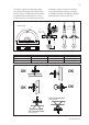
Control Drawing CSA
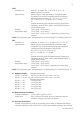
The ISC40S sensor shall be installed with
one of the Yokogawa transmitters model:
• ISC202S • IC200S • FLXA21
with following parameters:
ISC202S IC200S FLXA21
Uo 14.4 V 19.1 V 11.76 V
Io 88 mA 162 mA 60.6 mA
Po 317 mW 178 mW
Lo 4.5 mH 800µH 8 mH
Co 600 nF 254nF 100 nF
or
To a CSA approved intrinsically safe
apparatus meeting the entity parameters of
the ISC40S: Uo ≤ 19.1V
Io ≤ 170mA
Po ≤ 0.8W
Co ≥ Ci + C(cable)
Lo ≥ Li + L(cable)
The effective inductive capacitance Ci and the
effective induced inductance Li of the sensor
depends only upon the properties and the
length of the connected cable (max 50m).
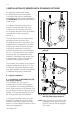
When installing this equipment, follow the
manufacturer’s control drawing. Installing
should be in accordance with Canadian
Electrical Code Part 1 or CEC Part1.
Warning: To prevent ignition of flammable or combustible atmospheres, disconnect power
before servicing or read, understand and adhere to the manufacturer’s live maintenance
procedures.
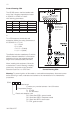
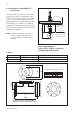
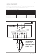
Fig 2: FF1-K1244QY
Control Drawing CSA
ISC40 sensor
terminals 11-17.
Maximum cable
length: 50m.
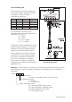
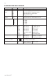
ISC40-
-
-
Cable length
in meters, any number between 1 and 50 meters
Temperature Element
T1 PT1000
T3 30k thermistor
Plastic and adaption code
GG Glass filled PEEK, general model
GR Glass filled PEEK, retractable model
GS Glass filled PEEK, shaft model
TG PFA, general model