User’s Manual Model ISC40G(S) Sensors and Fittings for Inductive Conductivity Measurement IM 12D8J2-E-E 16th edition
(BG) Всички улътвания за продукти от серията ATEX Ex ce лредлагат на английски език. Ако се нуждаете oт улътвания за продукти oт серията Ex на родния ви eзик, ce свържете c най-близкия oфис или представителство на фирма Yokogawa. (CZ) Všechny uživatelské příručky pro výrobky, na něž se vztahuje nevýbušné schváleni ATEX Ex, jsou dostupné v angličtině. Požadujete-li pokyny týkající se výrobků s nevýbušným schválením ve vašem lokálním jazyku, kontaktujte prosím vaši nejbližší reprezentačni kancelář Yokogawa.
(LV) Visas ATEX Ex kategorijas izstrâdâjumu Lietoðanas instrukcijas tiek piegâdâtas angïu valodâs. Ja vçlaties saòemt Ex ierîèu dokumentâciju citâ valodâ, Jums ir jâsazinâs ar firmas Jokogava (Yokogawa) tuvâko ofisu vai pârstâvi. (LT) Visos gaminiø ATEX Ex kategorijos Eksploatavimo instrukcijos teikiami anglø kalbomis. Norëdami gauti priestaisø Ex dokumentacijà kitomis kalbomis susisiekite su artimiausiu bendrovës Yokogawa biuru arba atstovu.
Contents 1 INTRODUCTION 7 2 GENERAL SPECIFICATIONS 9 1.1 1.2 1.3 1.4 General Unpacking and Checking Warranty and Service Serial Number definition 7 7 7 8 2.1 Measuring elements 2.2 Materials 2.3 Functional specifications (at 25°C) 2.4 Dynamic specifications 2.5 Operating range 2.6 Regulatory standards 2.7 Shipping details 2.8 Environmental conditions 2.
10 ISC40FF – FLOW FITTING 27 11 ISC40FD – IMMERSION FITTING 31 12 Chemical Compatibility Chart 35 10.1 General Specifications 10.1.1 Materials 10.1.2 Operating range 10.1.3 Shipping details 10.1.4 Process connections 10.2 Installation of ISC40 sensor in ISC40FF 10.3 Dimensions ISC40FF 10.4 Modelcode ISC40FF 10.5 Spareparts ISC40FF 11.1 General Specifications 11.1.1 Materials 11.1.2 Operating range 11.1.3 Process connections 11.2 Installation of ISC40 sensor in ISC40FD 11.3 Dimensions ISC40FD 11.
IM 12D8J2-E-E
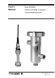
1 INTRODUCTION 1.1 General The sensor and fitting program for inductive conductivity measurement (model ISC40) is designed to meet the most common installation requirements in terms of material compatibility, process connections and flow dynamics. The various installation possibilities are described and illustrated in this manual. The following categories of installation can be recognised: 1. Direct mounting of sensors in tank wall or customer supplied flanges 2.
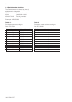
1.4 Serial Number definition The Serial Number is defined by nine (9) alphanumeric characters: X1X2 Production Location X3X4 Year/Month code X5X6 X7X8 X9 Tracking number Example: N1B600028 Table 1: Production year according to DIN. IEC 60062 Year Yearcode 2012 C 2013 D 2014 E 2015 F 2016 H 2017 J 2018 K 2019 L 2020 M 2021 N 2022 P 2023 R IM 12D8J2-E-E Year Yearcode 2024 S 2025 T 2026 U 2027 V 2028 W 2029 X 2030 A 2031 B 2032 C 2033 D 2034 E 2035 F Table 2: Production month code according to DIN.
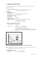
2 GENERAL SPECIFICATIONS The ISC40 inductive conductivity sensor is suitable for use with the Yokogawa inductive conductivity analyzers. 2.1 Measuring elements : Toroïds with high permeability magnetic material Pt1000 or 30k temperature element 2.
2.5 Operating range Conductivity : 0 – 2000 mS/cm at actual process temperature. Note: T he sensor has an error (0.5 µS/cm for PEEK model, 1.0 µS/cm for PFA model) that must be considered when application is chosen. Temperature : - 20°C to 130°C (-4°F to 266°F) for PEEK sensor -20°C to 100°C (-4°F to 212°F) for PFA sensor Pressure : 0 to 20 bar (0 to 290 PSIG) for PEEK sensor 0 to 10 bar (0 to 145 PSIG) for PFA sensor.
CSA Certificate no. : 2447837 IS, Class I Div. 1, GP A, B, C, D T4…T6 Master Contract no 182892 Electrical data : Sensor output circuits (permanently connected cable) connected to a certified intrinsically safe circuit with the following maximum values: Uo = 19.1 V; Io = 170 mA; Po = 0.8 W; Co≥ Ci + Ccable; Lo≥ Li + Lcable or certified intrinsically safe Yokogawa Inductive Conductivity transmitter model FLXA21 series, model ISC202S series or model IC200S series Ambient : T6 for Tamb.
Control Drawing CSA The ISC40S sensor shall be installed with one of the Yokogawa transmitters model: • ISC202S • IC200S • FLXA21 with following parameters: Uo Io Po Lo Co ISC202S IC200S 14.4 V 19.1 V 88 mA 162 mA 317 mW 4.5 mH 800µH 600 nF 254nF FLXA21 11.76 V 60.6 mA 178 mW 8 mH 100 nF ISC40 sensor terminals 11-17. Maximum cable length: 50m. or To a CSA approved intrinsically safe apparatus meeting the entity parameters of the ISC40S: Uo ≤ 19.1V Io ≤ 170mA Po ≤ 0.
Control Drawing FM The ISC40S sensor shall be installed with one of the Yokogawa transmitters model: • ISC202S • IC200S • FLXA21 with following parameters: ISC202S IC200S FLXA21 Uo 14.4 V 19.1 V 11.76 V Io 88 mA 162 mA 60.6 mA Po 317 mW 178 mW Lo 4.5 mH 800µH 8 mH Co 600 nF 254nF 100 nF or To a FM approved intrinsically safe apparatus meeting the entity parameters of the ISC40S: Uo ≤ 19.1V Io ≤ 170mA Po ≤ 0.
3 INSTALLATION OF SENSOR WITH STANDARD OPTIONS For optimum measurement results, the ISC40 sensor should be installed in a location that offers an acceptable representation of the process composition and DOES NOT exceed the specifications of the sensor. A It is important that the process flow is directed through the hole in the donut of the sensor. For this reason the flats on the sensor top part have to be installed perpendicular on the process flow (see fig. 4).
The sensor cable and mounting thread are pulled through the hole of the flange, and the sensor is sealed from the process by tightening the mounting nut. Turning of the sensor by the torque forces can be avoided by using a wrench on the flats on top of the sensor (see fig. 5). Sensor is installed correctly if the flats are aligned perpendicular on the process flow. Flange dimensions in mm (inches) O-ring FLANGE ADAPTER d 26.65 x 2.62 O-ring 40.87 x 3.53 26.57 x 3.53 116 (4.56) 40.64 x 5.
3.1.2 I nstallation of ISC40G(S)-TG with T-piece The ISC40G(S)-TG sensor is a PFA sensor which can be used in combination with a T-piece of which the innerside is lined with PFA. This can be done using option /TFD (sealing material with stainless steel DN65 PN10 flange), or by option /TFN (sealing material) if the stainless steel flange DN65 PN10 is already available. Both options are available as sparepart. DN65 PN10 flange TFM ring O-ring 29.74 x 3.53 Goretex seal 123 (4.
3.1.3 I nstallation of ISC40G(S)-GS with flange adapters plastic nut The ISC40G(S)-GS sensor is designed for sanitary applications. For these applications special process connections are necessary. tube Mounting procedure: • Screw the tube completely in the stainless steel nut. • Thread the sensor cable through the flange adapter parts in the right sequence. • Screw the tube hand tight into the flange, a mechanical stop will be felt.
4 DIMENSIONS ISC40 SENSOR Unit: mm (inches) ø17 (0.67”) nut G3/4 viton gasket For mounting in ISC40PR retractable fitting 124 (4.88") Minimum hole to fit sensor through: GG Ø48 (1.89") TG Ø50 (1.99”) 182 (7.16") Ø40 (1.57") Minimum hole to fit sensor through: Ø48 (1.89") m19 x 1.5 55 (2.16") Ø47 (1.85") GG Ø47 (1.85”) TG Ø49 (1.93”) Fig 12: ISC40G(S)-GG (TG) Fig 13: ISC40G(S)-GR ISC40-PR For mounting in SFT, STC 1 and STC 2 Fittings. Ø20 (0.78") 193 (7.60") Stainless steel 77 (3.
5 WIRING ISC40 SENSOR The ISC40 sensor is provided with a fixed cable. The connections of this dual coax cable and the Yokogawa Inductive Conductivity analyser are given in table 1. Table 1: Definition cable and analyzer Cable wire color Red Blue Yellow White White (shield) Brown Brown (shield) ISC analyser terminal # 11 12 14 15 16 13 17 Signal description Temperature Temperature Shield Primary coil Primary coil Secondary coil Secondary coil ISC40 sensor terminals 11-17. Maximum cable length: 50m.
6 MODELCODE ISC40 SENSOR Model Code Suffix Option ISC40G Sensor -GG type -GR -GS -TG Temperature -T1 sensor -T3 Cable length -3 -5 -10 -15 -20 Options for Sensor Flange adapters -GG, -TG /SFA /SFD /STW /S2W /TFD /TFN Flange adapters for -GS /SFT /STC1 /STC2 Protection Hose for-TF, -TG, -GG /PH Certificates /M /Q IM 12D8J2-E-E Description General purpose inductive conductivity sensor Glass filled PEEK, general model Glass filled PEEK, retractable mo
7 SPAREPARTS ISC40 SENSOR Part no. Description K1500AM Gasket K1500AL Mounting nut Parts ISC40 sensor Material Viton AISI 316 SS Options ISC40 sensor, Flange adapters Part no.
8 EU DECLARATION OF CONFORMITY We: Y okogawa Europe B.V.
9 ISC40FS – FLOW FITTING SUBASSEMBLY 9.1 General Specifications 9.1.1 Materials Wetted parts Model ISC40FS-FCSA Model ISC40FS-PCSA Model ISC40FS-SCSA Model ISC40FS-SCWN : : : : PVDF (Kynar); Viton Polypropylene; Viton AISI 316 SS; Viton AISI 316 SS; Viton : : : : Max. Max. Max. Max. Non-wetted parts Nut : AISI 304 SS 9.1.
O-ring 40.64 x 5.33 O-ring 40.64 x 5.33 Holder Holder O-ring 26.57 x 3.53 O-ring 26.57 x 3.53 Ring DN50 Ring DN50 Fig 16: I SC40 sensor in weld-in subassembly ISC40FS-SCWN Fig 15: I SC40 sensor in screw-in subassembly ISC40FS-SCSA 9.3 Dimensions ISC40FS Rd 78 x 1/6 acc. DIN 405 Rd 78 x 1/6 acc. DIN 405 Rd 78 x 1/6 acc. DIN 405 2" NPT acc. ANSI B.20.1 88 (3.46) 64 (2.52) 64 (2.52) Ø 50 /SCWN 2" NPT acc. ANSI B.20.
9.4 Modelcode ISC40FS Model Suffix Option Description ISC40FS Flow fitting subassembly Material -F PVDF -P Polypropylene -S Stainless Steel Process -CS Dairy Coupling screw-in* connection -CW Dairy Coupling welded* Thread type -A NPT NPT or R -N No thread (for weld-in couplings) Options /M Material certificate 3.1. EN 10024 (for wetted metal parts only) * Note: according to Din 11851 9.5 Spareparts ISC40FS Parts ISC40FS subassembly Part no.
10 ISC40FF – FLOW FITTING 10.1 General Specifications 10.1.1 Materials Wetted parts Model ISC40FF-S Model ISC40FF-P Model ISC40FF-F Non-wetted parts : : : : AISI 316 SS; Viton Polypropylene; Viton PVDF (Kynar); Viton AISI 304 SS or AISI 316 SS 10.1.2 Operating range Temperature Model ISC40FF-S Model ISC40FF-P Model ISC40FF-F Pressure Model ISC40FF-S Model ISC40FF-P Model ISC40FF-F 10.1.3 Shipping details Package size (LxWxH) Package weight (max) : Max. 150°C (302°F) : Max. 100°C (212°F) : Max.
70 (2.75) 70 (2.75) O-Ring 40.64 x 5.33 Holder Ø 10 (0.4) 4x O-Ring 26.57 x 3.53 Ring DN50 pipe mount (horizontal) pipe mount (vertical) Fig 18: I nstallation of ISC40 sensor in flow fitting Fig 19: Pipe/wall mounting kit Note: The ISC40 sensor type -TG does not fit in the model ISC40FF-S. 127 (5) 186 (7.32) d 10.3 Dimensions ISC40FF L2 Option ø 90 (3.55) L1 L2 d /FF1 156 (6.14) 211 (8.31) 65 (2.56) /FF2 145 (5.71) 200 (7.87) 85 (3.35) /FF3 156 (6,14) 211 (8,31) 60,5 (2.
58 (2.3) d 158 (6.22) 28 39 (1.6) Option Direction of FLOW L1 d /FS1 260 (10.24) 65 (2.56) /FS2 280 (11.02) 85 (3.35) /FS3 260 (10.24) 60,5 (2.38) /FS4 280 (11.02) 79,2 (3.12) Ø 54 (2.12) 120 (4.72) L1 Fig 21: Flow fitting ISC40FF-S 10.
10.5 Spareparts ISC40FF Options ISC40FF Flow fitting, flange adapters Part no.
11 ISC40FD – IMMERSION FITTING 11.1 General Specifications 11.1.1 Materials Wetted parts without options Model ISC40FD-S : AISI 316 SS, Viton Model ISC40FD-V : C-PVC, Viton Flange ISC40FD-S-**-SF* : AISI 316 SS Non-wetted parts Tube pigtail : plastic 11.1.2 Operating range Temperature Model ISC40FD-S Model ISC40FD-V Pressure Model ISC40FD-S Model ISC40FD-V : Max. 150°C (302°F) : Max. 80°C (176°F) : Max. 10 bar (150 PSI) at operating temperature : Max. 2 bar (30 PSI) at 20°C (68°F) Max.
ISC40FD-S ISC40FD-V Guide pipe Ø 48,6 x 600 (Ø1.9 x 24") Min: 110 (4.35") Max: 515 (20") O-Ring 44.17 x 1.78 O-Ring 39.35 x 2.62 2-inch Stanchion (Vertical) O-Ring 26.57 x 3.53 Fig 22: I nstallation of ISC40 sensor in immersion fitting.
Alternative ways of mounting the immersion fitting are: • Guide pipe To facilitate this type of mounting the immersion fitting has a larger diameter at the top. The user supplied guide pipe (internal diameter > 52 mm) is fitted to the wall or mounting rail. The immersion fitting slides into this guide pipe and therefore the sensor can be easily removed for inspection. • Platform mounting Sometimes there is a walking platform that can be used to mount the immersion fitting.
11.4 Modelcode ISC40FD Model code Suffix code Option code Description ISC40FD Immersion fitting Material -S AISI 316 Stainless steel -V PVC-C Insertion length Between 05 to 20 Example: 05 = 0.5 m / 20 = 2.
12 Chemical Compatibility Chart 20 60 20 60 100 20 60 100 20 60 100 XXX OOO XXX OOO XXX OOO - - - OOO - - - OOO - - - XXX OOX XXX - - OOO - - OOO - - - - - OOO XXX OOO OOO XX - - - OOO - - - OOO OOX - - OOX - - XXX - - OOO OOO OOO OOO OOO OOO OOO XXX OOO XXX XXX OOO XXX OOO - - - OOO OOO - - OOO OOO XXX OOO OOO OOO XXX OOO XXX OOO XXX OOO - - - OOO OOO OOO XXX OOX OOO OOO X X X OOO X - OOO OOO OOO - - OOX XXX OOO OOO PFA 20 60 10 OOO 50 OOO 95 OX fuming - - Hydrochloric acid 10 OOO sat.
IM 12D8J2-E-E
YOKOGAWA ELECTRIC CORPORATION World Headquarters 9-32, Nakacho 2-chome, Musashino-shi Tokyo 180-8750 Japan www.yokogawa.com YOKOGAWA ELECTRIC ASIA Pte. LTD. 5 Bedok South Road Singapore 469270 Singapore www.yokogawa.com/sg YOKOGAWA CORPORATION OF AMERICA 2 Dart Road Newnan GA 30265 USA www.yokogawa.com/us YOKOGAWA CHINA CO. LTD. 3F Tower D Cartelo Crocodile Building No.568 West Tianshan Road Changing District Shanghai, China www.yokogawa.