
User Manual


<2. Instruction for Replacement of the Heater Unit>
2-3
IM 11M12A01-21E
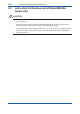
5. Assembling of Terminal Box and Wiring
Reassemble in reverse order to the above disassembly procedure.
How to identify the wires from the heater strut assembly :
Two wires coming from the ceramic insulator are heaters’. Single-core wire is CELL+. One of two-core
wires with semitransparent silicone tube is TC+ and the other is TC-. (If wire markers are attached to
each wire, connect wires to the corresponding terminal.
6. Installing of the Sensor (Cell)
Install the U-shaped pipe support, the U-shaped Pipe, the Filter and the Sensor (Cell) according to
Section 2.1.3 ” Part Assembly Procedure of Sensor Assembly”. Heater strut assembly ㉓ is shipped
with a new contact.
⑧
⑩
⑬
⑭
⑮
TCCELL CJ
1 23 45 6
87
H
T
R
F2.2.1E.ai
①
⑪
⑫
⑯
Bolt
Washer
U-shaped
pipe support
U-shaped
pipe
Filter
Sensor (Cell)
CELL+
Metal O-ring
Contact
TC-
TC+
Turn to
remove
screw
Index jig with
notches
in screw
Grip jig
in spanner
and turn to
unscrew
A
A
View A-A
⑭
⑳
⑬
⑲
⑰
⑱
Figure 2.2 Installation of Model ZR22A HEATER UNIT
when reference gas is natural convection or instrument air (sufx code-A)