User’s Manual Model ZR22A, ZR202A Heater Assembly IM 11M12A01-21E R IM 11M12A01-21E 3rd Edition
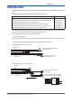
i Introduction The ZR22A and ZR202A Heater Assemblies for ZR22G, ZR22S, ZR202G and ZR202S are described here. The ZR22G, ZR22S, ZR202G and ZR202S manuals are listed below. User’s Manual IM No.
ii CAUTION The cell (sensor) at the tip of the probe is made of ceramic (zirconia element). Do not drop the equipment or subject it to pressure stress. • Do NOT allow the sensor (probe tip) to make contact with anything when installing the analyzer. • Avoid water dropping directly on the probe (sensor) of the analyzer when installing it. • Check the calibration gas piping before introducing the calibration gas to ensure that there is no leakage of the gas.
iii (2) Safety and Modification Precautions Follow the safety precautions in this manual when using the product to ensure protection and safety of personnel, product and system containing the product. The following safety symbols and wordings are used on the product as well as in this manual. (3) The following safety symbols are used in this manual. Throughout this user’s manual, you will find several different types of symbols are used to identify different sections of text.
iv After-Sales Warranty n Do not modify the product. n Yokogawa warrants the product for the period stated in the pre-purchase quotation. Yokogawa shall conduct defined warranty service based on its standard. n During the warranty period, for repair under warranty carry or send the product to the local sales representative or service office. Yokogawa will replace or repair any damaged parts and return the product to you.
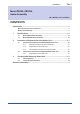
Toc-1 Model ZR22A, ZR202A Heater Assembly IM 11M12A01-21E 3rd Edition CONTENTS Introduction...............................................................................................................i For the safe use of this equipment................................................................................ ii After-Sales Warranty...................................................................................................... iv 1. 2. Specifications.......................
Blank Page
<1. Specifications> 1. Specifications 1.1 Model ZR22A Heater Assembly 1-1 Model and Codes Style: S2 Model Suffix code Option code ZR22A --------- ----------- Heater Assembly for ZR22G Length (*1) -015 -040 -070 -100 -150 -200 -250 -300 --------------------------------------------------------------------------------- 0.15 m 0.4 m 0.7 m 1m 1.5 m 2m 2.
1-2 <1. Specifications> 1.2 Model ZR202A Heater Assembly Model and Codes Model Suffix code Option code Description ZR202A --------- ----------- Heater Assembly for ZR202G Length (*1) -040 -070 -100 -150 -200 -250 -300 ----------------------------------------------------------------------- 0.4 m 0.7 m 1m 1.5 m 2m 2.5 m 3m --------------------- With Jig None ----------- Always -A Jig for change -A -N - -A (*2) *1 Suffix code of length should be selected as same as ZR202G installed.
2-1 <2. Instruction for Replacement of the Heater Unit> 2. Instruction for Replacement of the Heater Unit 2.1 Instruction for Replacement of Model ZR22A Heater Unit CAUTION • • • 2.1.1 Allow adequate time for the sensor (cell) and heater assembly to cool before replacing them, or you may get burnt. When removing the cell, the metal O-ring should be replaced with a new one. Never reuse a metal O-ring. Once-used metal O-ring should be replaced with a new one.
2-2 <2. Instruction for Replacement of the Heater Unit> CAUTION If the heater strut assembly cannot be removed because a screw has fused to its thread, one of our service representatives can fix it. 2.1.2 Replacement of the Heater Unit 1. Removing of the Sensor (Cell) Remove the U-shaped pipe support, the U-shaped pipe, the Filter and the Sensor (Cell) according to Sec. 2.1.1 “Removal procedures for Sensor Assembly”. 2.
2-3 <2. Instruction for Replacement of the Heater Unit> 5. Assembling of Terminal Box and Wiring Reassemble in reverse order to the above disassembly procedure. How to identify the wires from the heater strut assembly : Two wires coming from the ceramic insulator are heaters’. Single-core wire is CELL+. One of two-core wires with semitransparent silicone tube is TC+ and the other is TC-. (If wire markers are attached to each wire, connect wires to the corresponding terminal. 6.
2-4 <2. Instruction for Replacement of the Heater Unit> ⑯ A ⑭ ⑭ ⑭ ⑩ ⑪ ⑫ A ⑬ ⑮ Grip jig in spanner and turn to unscrew Contact Metal O-ring Bolt U-shaped U-shaped pipe pipe support Washer Index jig with notches in screw Turn to remove screw ⑧ Sensor (Cell) ① Filter TC+ View A-A CELL + TC - ⑰⑱ 1CELL 23 TC45 CJ6 ⑲ ⑬ 7HTR8 ⑭ ⑳ F2.2.2E.ai Figure 2.
2.1.3 2-5 <2. Instruction for Replacement of the Heater Unit> Part Assembly Procedure of Sensor Assembly (1) First, install the contact. Being careful not to cause irregularities in the pitch of the coil spirals (i.e., not to bend the coil out of shape), place it in the ringed groove properly so that it forms a solid contact. Groove in which the contact (E7042BS) is placed.
2-6 <2. Instruction for Replacement of the Heater Unit> 2.2 Instruction for Replacement of Model ZR202A Heater Unit CAUTION • Allow adequate time for the sensor (cell) and heater assembly to cool before replacing them, or you may get burnt. • When removing the cell, the metal O-ring should be replaced with a new one. Never reuse a metal O-ring. Once-used metal O-ring should be replaced with a new one. • The grease used for rubber O-rings lubricant see ⑭ , ㉑ , ㉑ etc. in Figure 2.
2.2.1 2-7 <2. Instruction for Replacement of the Heater Unit> Replacement of the Heater Unit 1. Removing of the Sensor (Cell) Remove the U-shaped pipe support, the U-shaped pipe, the Filter and the Sensor (Cell) according to chapter 2.11 ”Removal procedures of the sensor assembly”. 2. Removing of the Converter Case (1) Remove the two screws ⑮ that fasten the cover ⑫ and slide it to the flange side. (2) Remove the four bolts ⑩ and the converter ⑯.
2-8 <2. Instruction for Replacement of the Heater Unit> ⑱ ⑪ ⑩ ⑭ A ⑫ ⑬ ⑮ A Contact Metal O-ring Grip jig in Spanner and turn to unscrew Turn to remove screw Index jig with notches in screw ⑧ U-shaped pipe support U-shaped pipe Washer Bolt Sensor (Cell) ① Filter View A-A ⑰ ⑱ ⑲ ⑬ ⑭ ⑳ Figure 2.5 Installation of Model ZR202A HEATER UNIT IM 11M12A01-21E F2.4E.
3-1 <3. Checking After Replacing Heater Unit> 3. Checking After Replacing Heater Unit 3.1 Checking Wiring Model ZR22A (Separate type heater) uses screw termination. TC + TC – CELL + 1 CELL 2 3 TC 4 5 7 HEATER CJ H TR 6 8 F3.1E.ai Figure 3.1 Model ZR22A Terminal wiring diagram Model ZR202A (Integrated type heater) uses a connector. Signal connector Connector for heater Solenoid valve connector when ZR20H automatic calibration unit used. Zero Span F3.2E.ai Figure 3.
Blank Page
i Revision Information Model ZR22A, ZR202A Heater Assembly Title: Manual No.: IM 11M12A01-21E Edition Date 1st Aug. 2001 Remark (s) Newly published 2nd July 2003 Revised Section Style of ZR22A changed to S2 3.1 Instruction for replacement for ZR22A Heater Unit some changed.
ii n If you want have more information about Yokogawa products, you can visit Yokogawa’s home page at the following website. Home page: http://www.yokogawa.com/an/ n Written by Environmental & Analytical Products PMK Dept. IA Div., Product Business Center Yokogawa Electric Corporation n Published by Yokogawa Electric Corporation 2-9-32 Nakacho, Musashino-shi, Tokyo 180-8750, JAPAN n Printed by KOHOKU PUBLISHING & PRINTING INC.