
Owner manual


Table Of Contents
- Introduction
- CONTENTS
- 1. Overview
- 2. Specifications
- 2.1 General Specifications
- 2.2 General use Separate type Detector and Related Equipment
- 2.3 Separate type Detector for High Temperature and Related Equipment
- 2.4 ZR402G Separate type Converter
- 2.5 ZA8F Flow Setting Unit and ZR40H Automatic Calibration Unit
- 2.6 ZO21S Standard Gas Unit
- 2.7 Other Equipments
- 2.7.1 Dust Filter for the Detector (K9471UA)
- 2.7.2 Dust Guard Protector (K9471UC)
- 2.7.3 Ejector Assembly for High Temperature (E7046EC, E7046EN)
- 2.7.4 Stop Valve (L9852CB, G7016XH)
- 2.7.5 Check Valve (K9292DN, K9292DS)
- 2.7.6 Air Set
- 2.7.7 Zero Gas Cylinder (G7001ZC)
- 2.7.8 Cylinder Pressure Reducing Valve (G7013XF, G7014XF)
- 2.7.9 Case Assembly for Calibration Gas Cylinder (E7044KF)
- 2.7.10 ZR22A Heater Assembly
- 3. Installation
- 3.1 Installation of General-purpose Detector
- 3.2 Installation of High Temperature Detector (ZR22G-015)
- 3.3 Installation of the ZR402G Converter
- 3.4 Installation of ZA8F Flow Setting Unit
- 3.5 Installation of ZR40H Automatic Calibration Unit
- 3.6 Installation of the Case Assembly(E7044KF)
- 3.7 Insulation Resistance Test
- 4. Piping
- 5. Wiring
- 6. Components
- 7. Startup
- 7.1 Checking Piping and Wiring Connections
- 7.2 Checking Valve Setup
- 7.3 Supplying Power to the Converter
- 7.4 Touchpanel Switch Operations
- 7.5 Confirmation of Converter Type Setting
- 7.6 Confirmation of Detector Type Setting
- 7.7 Selection of Sample Gas
- 7.8 Output Range Setting
- 7.9 Setting Display Item
- 7.10 Checking Current Loop
- 7.11 Checking Contact I/O
- 7.12 Calibration
- 8. Detailed Data Setting
- 9. Calibration
- 10. Other Functions
- 11. Inspection and Maintenance
- 12. Troubleshooting
- Customer Maintenance Parts List CMPL 11M12A01-02E
- Customer Maintenance Parts List CMPL 11M12C01-01E
- Customer Maintenance Parts List CMPL 11M12A01-11E
- Customer Maintenance Parts List CMPL 11M03B01-10E
- Customer Maintenance Parts List CMPL 11M03B01-05E
- Customer Maintenance Parts List CMPL 11M03D01-01E
- Revision Information
<8. Detailed Data Setting>
8-4
IM 11M12A01-02E
8.2.2 Preference Order of Output Hold Value
The output hold value takes the following preference order:
On error occurrence
Under calibration or during blow back
Under maintenance
During warm-up
Preference order (high)
8.2.2.siki
For example, if the output current is set to 4 mA during maintenance, and no output-hold output
for during calibration is preset, the output is held at 4 mA during the maintenance display.
However, the output hold is released at the time of starting the calibration, and the output will be
again held at 4 mA after completing the calibration and when the hold (output stabilization) time
elapses.
8.2.3 Output Hold Setting
To set the output hold, follow these steps:
(1) Press the [Setup] key in the Basic panel display to display the Execution/Setup display.
Then select “Commissioning” in the Execution/Setup display. Next, select the “mA-output
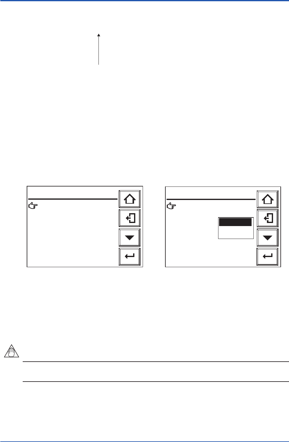
setup” and then the “mA-outputs presets” display as shown in Figure 8.2.
Warm up: 4mA
Preset value: 4 . 0 mA
Maintenance: Hold
Preset value: 4 . 0 mA
Cal.blow back: Hold
Preset value: 4 . 0 mA
Error: Preset
Preset value: 3 . 4 mA
Enter
mA-outputs presets
F8.1E.ai
Warm up: 4mA
Preset value: 4 . 0 mA
Maintenance: Hold
Preset value: 4.0mA
Cal.blow back: Hold
Preset value: 4 . 0 mA
Error: Preset
Preset value: 3 . 4 mA
Enter
mA-outputs presets
Non-Hold
Hold
Preset
F8.2E.aiS
Figure 8.1 mA-outputs presets Display Figure 8.2 Selecting Maintenance
(2) From this display (Fig. 8.2), select the desired display. Figure 8.3 shows an example
of selecting “Maintenance”. Select the desired output status.
(3) If a preset value is selected, set the corresponding output current. If you select a preset
value just below Maintenance on the screen, the numeric-data entry display will appear.
Enter the current value you want. To set 10 mA, type in 010 and press the [Enter] key to
complete the setting. The setting range is from 2.4 to 21.6 mA.
NOTE
“Error” of mA-outputs presets is not displayed when option code “/C2” or “/C3” (NAMUR NE 43
compliant) is specied.
8th Edition : Jan.13,2012-00