
Owner manual


Table Of Contents
- Introduction
- CONTENTS
- 1. Overview
- 2. Specifications
- 2.1 General Specifications
- 2.2 General use Separate type Detector and Related Equipment
- 2.3 Separate type Detector for High Temperature and Related Equipment
- 2.4 ZR402G Separate type Converter
- 2.5 ZA8F Flow Setting Unit and ZR40H Automatic Calibration Unit
- 2.6 ZO21S Standard Gas Unit
- 2.7 Other Equipments
- 2.7.1 Dust Filter for the Detector (K9471UA)
- 2.7.2 Dust Guard Protector (K9471UC)
- 2.7.3 Ejector Assembly for High Temperature (E7046EC, E7046EN)
- 2.7.4 Stop Valve (L9852CB, G7016XH)
- 2.7.5 Check Valve (K9292DN, K9292DS)
- 2.7.6 Air Set
- 2.7.7 Zero Gas Cylinder (G7001ZC)
- 2.7.8 Cylinder Pressure Reducing Valve (G7013XF, G7014XF)
- 2.7.9 Case Assembly for Calibration Gas Cylinder (E7044KF)
- 2.7.10 ZR22A Heater Assembly
- 3. Installation
- 3.1 Installation of General-purpose Detector
- 3.2 Installation of High Temperature Detector (ZR22G-015)
- 3.3 Installation of the ZR402G Converter
- 3.4 Installation of ZA8F Flow Setting Unit
- 3.5 Installation of ZR40H Automatic Calibration Unit
- 3.6 Installation of the Case Assembly(E7044KF)
- 3.7 Insulation Resistance Test
- 4. Piping
- 5. Wiring
- 6. Components
- 7. Startup
- 7.1 Checking Piping and Wiring Connections
- 7.2 Checking Valve Setup
- 7.3 Supplying Power to the Converter
- 7.4 Touchpanel Switch Operations
- 7.5 Confirmation of Converter Type Setting
- 7.6 Confirmation of Detector Type Setting
- 7.7 Selection of Sample Gas
- 7.8 Output Range Setting
- 7.9 Setting Display Item
- 7.10 Checking Current Loop
- 7.11 Checking Contact I/O
- 7.12 Calibration
- 8. Detailed Data Setting
- 9. Calibration
- 10. Other Functions
- 11. Inspection and Maintenance
- 12. Troubleshooting
- Customer Maintenance Parts List CMPL 11M12A01-02E
- Customer Maintenance Parts List CMPL 11M12C01-01E
- Customer Maintenance Parts List CMPL 11M12A01-11E
- Customer Maintenance Parts List CMPL 11M03B01-10E
- Customer Maintenance Parts List CMPL 11M03B01-05E
- Customer Maintenance Parts List CMPL 11M03D01-01E
- Revision Information
<7. Startup>
7-13
IM 11M12A01-02E
7.11.2 Checking Calibration Contact Output
The calibration contacts are used for solenoid valve drive signals for the ZR40H Automatic
Calibration Unit. When using the ZR40H Automatic Calibration Unit, use the calibration contact
output to check that the wiring connections have been properly completed and check equipment
operation.
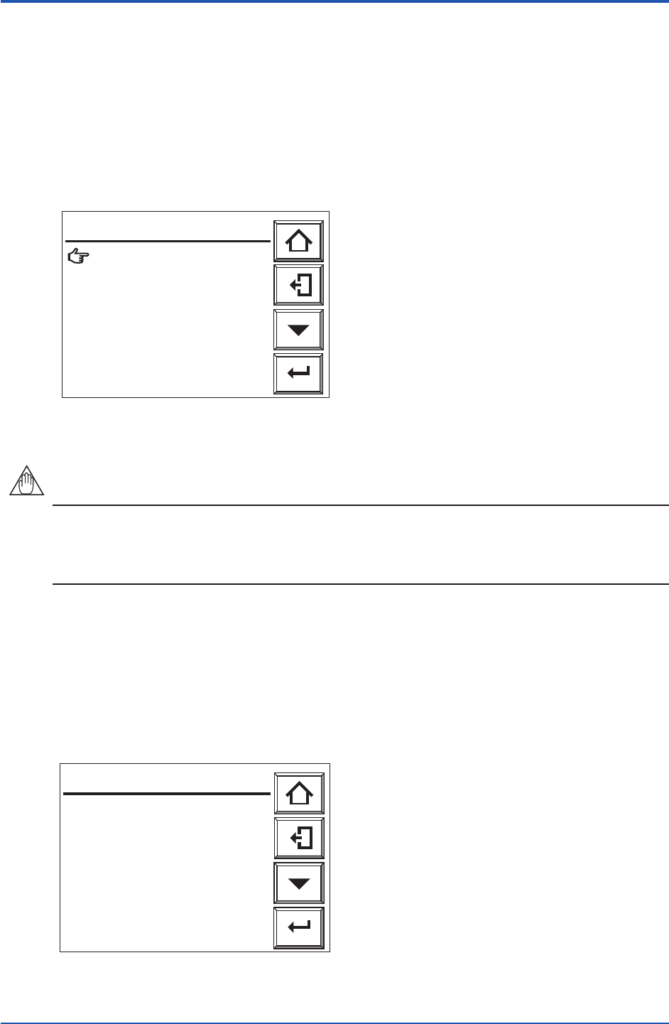
(1) Referring to Section 7.11.1, display the contact check display.
(2) Select the “Calibration contacts” to display the panel display as Figure 7.15.3 shows.
(3) Open the “Zero gas contact” and the “Span gas contact”. This will help check the automatic
calibration unit and wiring connections.
Zero gas contact : Open
Span gas contact : Open
Enter
Calibration contacts
F7.15.3E.ai
Figure 7.15.3 Calibration Contact Check Display
NOTE
“Open” and “Closed” displayed on the Calibration contacts display indicate actions of drive
contacts and are opposite to the valve open and close actions. If “Open” is displayed on the
Calibration contacts display, no calibration gas ows. If “Closed” is displayed on that display,
calibration gas ows.
7.11.3 Checking Input Contacts
(1) Referring to Section 7.11.1, display the contact check display.
(2) Display the “Input contacts” check display as Figure 7.15.4 shows. The “Open” or “Closed”
input contact in the display shows the current contact input terminal status and the display
changes according to the contact status. Using this enables you to check that the wiring
connections have been properly completed.
Input contact 1 : Open
Input contact 2 : Open
Enter
Input contacts
F7.15.4E.ai
Figure 7.15.4 Input Contact Check Display
8th Edition : Jan.13,2012-00