
Manual

<6. Conguration>
6-1
IM 01S01C01-01EN
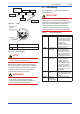
6. Conguration
This chapter describes how to adapt the function
and performance of the FVX110 to suit specic
applications. Because multiple devices are
connected to Fieldbus, it is important to carefully
consider the device requirements and settings
when conguring the system. The following steps
must be taken.
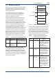
(1) Network design
Determines the devices to be connected to
Fieldbus and checks the capacity of the power
supply.
(2) Network denition
Determines the tag and node addresses for all
devices.
(3) Denition of combining function blocks
Determines how function blocks are combined.
(4) Setting tags and addresses
Sets the PD Tag and node addresses for each
device.
(5) Communication setting
Sets the link between communication
parameters and function blocks.
(6) Block setting
Sets the parameters for function blocks.
The following section describes in sequence each
step of this procedure. The use of a dedicated
conguration tool signicantly simplies this
procedure. Refer to Appendix 7 when the FVX110 is
used as Link Master.
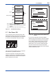
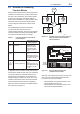
6.1 Network Design
Select the devices to be connected to the Fieldbus
network. The following are essential for the
operation of Fieldbus.
• Power supply
Fieldbus requires a dedicated power supply. It
is recommended that current capacity be well
over the total value of the maximum current
consumed by all devices (including the host).
Conventional DC current cannot be used as
this.
• Terminator
Fieldbus requires two terminators. Refer to
the supplier for details of terminators that are
attached to the host.
• Field devices
Connect the eld devices necessary for
instrumentation. The FVX110 has passed the
interoperability test conducted by The Fieldbus
Foundation. In order to properly start Fieldbus,
it is recommended that the devices used satisfy
the requirements of the above test.
• Host
Used for accessing eld devices. A minimum
of one device with the bus control function is
needed.
• Cable
Used for connecting devices. Refer to
“Fieldbus Technical Information” for details
of instrumentation cabling. Provide a cable
sufciently long to connect all devices. For
eld branch cabling, use terminal boards or a
connection box as required.
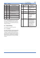
First, check the capacity of the power supply. The
power supply capacity must be greater than the
sum of the maximum current consumed by all
devices to be connected to Fieldbus. The maximum
current consumed (power supply voltage 9 V to
32 V) for the FVX110 is 15 mA (24 mA in Software
download operation). The cable used for the spur
must be of the minimum possible length.