
Manual

<Appendix 5. PID Block>
A5-5
IM 01S01C01-01EN
A5.4 PID Computation Details
A5.4.1 PV-proportional and -derivative
Type PID (I-PD) Control Algorithm
For PID control, the PID block employs the PV-
proportional and PV-derivative type PID control
algorithm (referred to as the I-PD control algorithm)
in Auto and RCas mode. The I-PD control algorithm
ensures control stability against sudden changes in
the setpoint, such as when the user enters a new
setpoint value. At the same time, the I-PD algorithm
ensures excellent controllability by performing
proportional, integral, and derivative control
actions in response to changes of characteristics
in the controlled process, changes in load, and
occurrences of disturbances.
In Cas mode, PV derivative type PID control
algorithm (referred to as the PI-D control algorithm)
is employed in order to obtain better performance
against the changes in the setpoint. The algorithm
is automatically switched by the block according
to the mode. A basic form of each algorithm is
expressed in the equation below.
∆MVn = K{∆PVn + (PVn - SPn) + ∆(∆PVn)}
∆T
Ti
Td
∆T
I-PD Control Algorithm (in Auto / RCas mode)
∆MVn = K{∆(PVn - SPn) + (PVn - SPn)
∆T
Ti
Td
∆T
PI-D Control Algorithm (in Cas mode)
+ ∆(∆PVn)}
Where,
ΔMVn = change in control output
ΔPVn = change in measured (controlled)
value = PVn - PVn-1
ΔT = control period = period_of_execution
in Block Header
K = proportional gain = GAIN (= 100/
proportional band)
Ti = integral time = RESET
Td = derivative time = RATE
The subscripts, n and n-1, represent the time
of sampling such that PVn and PVn-1 denote
the PV value sampled most recently and the PV
value sampled at the preceding control period,
respectively.
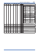
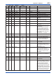
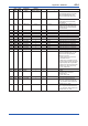
A5.4.2 PID Control Parameters
The table below shows the PID control parameters.
Parameter Description Valid Range
GAIN Proportional gain 0.05 to 20
RESET Integral time 0.1 to 10,000 (seconds)
RATE Derivative time 0 to innity (seconds)
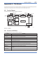
A5.5 Control Output
The nal control output value, OUT, is computed
based on the change in control output ΔMVn, which
is calculated at each control period in accordance
with the aforementioned algorithm. The PID block
in an FVX110 performs the velocity type output
action for the control output.
A5.5.1 Velocity Type Output Action
The PID block determines the value of the new
control output OUT by adding the change in control
output calculated in the current control period,
ΔMVn, to the current read-back value of the MV,
MV
RB
(BKCAL_IN).
This action can be expressed as:
ΔMVn’ = ΔMVn
*
(OUT_SCALE. EU100 – OUT_
SCALE. EU_0) / (PV_SCALE. EU_100 – PV_
SCALE. EU_0)
(Direct Acting is False in CONTROL_OPTS)
OUT = BKCAL_IN – ΔMVn’
(Direct Acting is True in CONTROL_OPTS)
OUT = BKCAL_IN + ΔMVn’
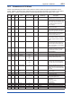
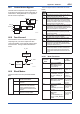
A5.6 Direction of Control Action
The direction of the control action is determined by
the Direct Acting setting in CONTROL_OPTS.
Value of Direct
Acting
Resulting Action
True The output increases when the input
PV is greater than the setpoint SP.
False The output decreases when the input
PV is greater than the setpoint SP.