Instruction Manual YOKOGAWA Model PH20 & FU20 pH/ORP Combination sensor IM 12B6J3-E-H 5th edition
TABLE OF CONTENTS 1. General . . . . . . . . . . . . . . 1-1. Introduction . . . . . . . . . . 1-2. Unpacking and Checking 1-3. Warranty and Service . . . . . . . . . . . . . . . . . . . . . . . . . . . . . . . . . . . . . . . . . . . . . . . . . . . . . . . . . . . . . . . . . . . . . . . . . . . . . . . . . . . . . . . . . . . . . . . . . . . . . . . . . . . . . . . . . . . . . . . . . . . . . . . . . . . . . . . . . . . . . . . . . . . . . . . . . . . . . . . . . .
IM 12B6J3-E-H
1 1. GENERAL 1-1. INTRODUCTION This instruction manual provides information for the installation and use of the FU20 and PH20, four-in-one wide body pH sensors. While both sensors can be used in a variety of applications, in general, the FU20 is the choice for the majority of typical wastewater and process applications. The PH20 with its patented "compensation panels", is selected when more aggressive chemicals (PVDF body) or varying process temperatures and pressures are present.
2 2. GENERAL SPECIFICATIONS PH20 2-1. Measuring elements 2-2. Construction materials Body Earthing pin O-ring Reference junction Cable : : : : pH glass electrode Silver chloride reference Solid platinum electrode Pt1000 temperature sensor. : : : : : PVDF Solid Platinum Viton Porous PTFE Coaxial with 4 extra leads 2-3.
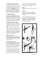
3 3. INSTALLATION OF PH20 For optimum measurement results, the PH20 should be installed in a location that offers an acceptable representation of the process composition and DOES NOT exceed the specifications of the sensor. The PH20 is designed with threads on either end of the body to allow installation via a selection of adapters, in a wide variety of applications. 3-1. Typical Installation The PH20 sensor is designed for in-line installation, via a bypass loop as an immersion assembly.
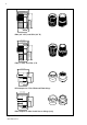
4 /FN4 /FR4 /SN3 /SR3 O-rings (2x) O-rings (2x) /FN4 /FR4 /SN3 /SR3 Figure 2.
5 Sensor cable Plug-in sensor /SF4 adapter FS40-S22-WE FS40-S22-TP Using the /SF4 adapter, the PH20 can be mounted in the standard range of conductivity flow fitting and sub-assemblies. The adapter can be mounted on the front thread or the back dependent on the required insertion depth. Front- and backend mounting in the FF40 Figure 3. Installation Examples using the /SF4 adapter Unit: mm (inches) ISO 228/1-G3/4 Ø 22 (0.86") ISO 228/1-G3/4 90 (3.54") 170 (6.70") 190.4 (7.50") 220.5 (8.
6 Unit: mm (inches) Ø 36.0 (1.42") 45 (1.77") 25.2 (1.0") Ø 30.0 (1.18") ISO 228/1-G3/4" 1" NPT /SN3 (3/4” NPT) and /SR3 (3/4” R) Ø 36.0 (1.42") Ø 30.0 (1.18") 45 (1.77") 25.2 (1.0") 20.0 (0.8") ISO 228/1-G3/4" 3/4" NPT /FN4 (1” NPT) and /FR4 (1”R) 30 (1.18") 15 (0.6") Ø 36.0 (1.42") ISO 228/1-G3/4" Ø 30 (1.18") /SF4 Adapter for FF40, FS40 and FD40 fittings Ø 38.0 (1.50") 29.5 (1.16") 15 (0.6") Ø 30.0 (1.18") ISO 228/1-G3/4" Ø 31 (1.
7 4. GENERAL SPECIFICATIONS FU20 4-1. Measuring elements 4-2. Construction materials Body Earthing pin O-ring Reference junction Cable : : : : pH glass electrode Silver chloride reference Solid platinum electrode Pt1000 temperature sensor. : : : : : PPS 40GF (Ryton) with glass filling Solid Platinum None Porous PTFE Coaxial with 4 extra leads 4-3.
8 5. INSTALLATION OF FU20 For optimum measurement results, the FU20 should be installed in a location that offers an acceptable representation of the process composition and DOES NOT exceed the specifications of the sensor. The FU20 is designed with threads on either end of the body 3/4" NPT or ISO 7/1 –R 3/4) to allow installation in a wide variety of applications. 5-1. Typical Installation The FU20 sensor is designed for in-line installation, via a bypass loop as an immersion assembly.
9 Process Flow Wrench Flats Do NOT overtighten Teflon Tape Teflon Tape Figure 7.
10 FU20 + FD40 FU20 + ADAPTER /SN3 /SR3 /FN4 /FR4 Fitting Process Flow /HCNF, SPRAY CLEANER O-ring Adapter ( /FPS ) FU20 O-ring Figure 8. Installation examples for the FU20 IM 12B6J3-E-H Cleaning Solution (water, acid, etc.
11 3/4" TAPERED THREAD Ø 26.0 (1.02") 3/4" TAPERED THREAD -NPT 19.7(0.78") 19.7 (0.78") 22.5 (0.89") 1” NPT or ISO 7/1-R1 51.0 (2.3") 150.0 (5.9") Ø 22.0 (0.86) /NSS, /NTI, /BSP, /BTI -FSM 10.0 (0.39") Figure 9. Dimensions FU20 Ø 35.5 (1.4") 25.0 (1") 99.0 (3.9") /NSS, /NTI, /BSP, /BTI 1” NPT or ISO 7/1-R1 Ø 39.0 (1.54") Figure 10. Dimensions 1” FU20 adapter Stainless Steel & Titanium /FPS 10.0 (0.4") 5.0 (0.2") 35.0 (1.38") Ø 30.0 (1.18") Ø 30.0 (1.18") Ø 36.0 (1.42") Figure 11.
12 6. WIRING pH (& ORP) WIRING DIAGRAM 11 6-1. Conventional pH (& ORP) Wiring Connect the PH20 or FU20 to the EXA or EXAxt PH Analyzer as shown (Fig 12). With this configuration, it is possible to measure ORP (or rH) at the same time (Refer to the EXA or EXAxt Manual for appropriate impedance jumper and Service Code settings).
13 7. GENERAL CALIBRATION & MAINTENANCE PROCEDURE 7-1. Calibration for pH measurement To calibrate a pH sensor, two buffer solutions with known pH values are required. It is recommended that one buffer solution have a value near to pH 7.00. Depending on the process value to be measured, the second buffer solution should be either acidic (below 7.00) or alkaline (above 7.00) area. Normally, the IEC buffers (4.01, 6.87 and 9.18) are used. The following is a very general 2-point calibration procedure. 1.
14 8. MODEL CODES Model Code PH20 Material Membrane Cable length Temp. element Suffix code Temp.
15 9. SPARE PARTS Spare part Description FU20 K1523DC K1547PK K1547PL K1547PM K1547PN K1500 FR K1500FS K1500FT /FPS Adapter for FF40, FS40 and FD40 fittings (PPO) /NSS 1” NPT, Stainless Steel adapter (Viton O-ring) /BSS ISO 7/1-R1, Stainless Steel adapter (Viton O-ring) /NTI 1” NPT, Titanium adapter (Viton O-ring) /BTI ISO 7/1-R1, Titanium adapter (Viton O-ring) Viton O-rings 29.82*2.62 (5 pcs) for 1” adapter EPDM O-rings 29.82*2.62 (5 pcs) for 1” adapter Silicone O-rings 29.82*2.
EUROPEAN HEADQUARTERS Yokogawa Europe B.V. Databankweg 20 3821 AL AMERSFOORT The Netherlands Tel. +31-33-4641 611 Fax +31-33-4641 610 E-mail: info@yokogawa.nl www.yokogawa-europe.com THE NETHERLANDS Yokogawa Nederland B.V. Hoofdveste 11 3992 DH HOUTEN Tel. +31-30-635 77 77 Fax +31-30-635 77 70 AUSTRIA Yokogawa Ges.m.b.H. Central East Europe Franzosengraben 1 A-1030 WIEN Tel. +43-1-206 340 Fax +43-1-206 34 800 BELGIUM Yokogawa Belgium N.V./S.A. Minervastraat 16 1930 ZAVENTEM Tel.