Instruction Manual Models FD30 / PB30 Fittings for the DO30G IM 12J6K4-E-E 5th edition
3 Table of contents 1. Introduction...............................................................................................................3 2. Unpacking and checking.........................................................................................3 3. Warranty and service................................................................................................3 4. Genral specifications................................................................................................
4 5 All defective goods need to be sent to the service of the sales organization for repair or replacement and the returned material should be accompanied by a letter of transmittal, which should include the following information: • Part number, Model code and Serial number • Date and number of sales order • Length of time of service and type of service • Description of the faulty operation of the device and the circumstances of the failure • Pressure, temperature, process composition and all other pr
6 7 5. Installation 5.2.2 Preparing the immersion fitting Prepare the immersion fitting by unscrewing the screw piece (4) from the bottom of the fitting. Remove the stopper (7), which can be discarded, and the conductive bushing (5). The screw piece will be used to fix the DO sensor in the fitting. When a flexible conduit (protecting hose) will be used, the pigtail part (2) can also be discarded. When an immersion fitting with cleaner is used the cleaning cage will be used to fix the DO-sensor.
8 5.2.4 Mounting the sensor cleaner (/JC option) • After fixing the sensor with the cleaning cage it is possible to screw the cleaner tubing on the cage using the swage lock coupling material provided with the cleaner. • It is recommended to fix the tubing to the holder using tie wraps. • Keep some flexible length of tubing for ease of maintenance. The cleaner can be used for both water and air. It is recommended to use a solenoid valve of the normally closed type with matching connections.
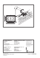
10 11 Dimensions Figure 7: Option /MS1 Figure 5: FD30 Figure 6: FD30 with flange 18 (0.70) Fill piece 78 (3.07) 125 (4.92) 168 (6.60) Guide pipe Ø 48,6 x 600 (Ø1.9 x 24") Min: 110 (4.35") Max: 515 (20") 18 (0.70) Ø 100 (3.94) 2-inch Stanchion (Vertical) L L Figure 8: PB30 rail mounting Ø 40 (1.57) Ø 40 (1.57) 2570 ± 50 (100 ± 2) Ø 50 (1.97) pipe/rail mounting DN 50 (2.00) 90 (3.54) Ø 50 (1.97) 344 (13.54) 70 (2.80) 70 (2.80) 90 (3.54) Ø 50 (1.97) 230 (9.
0 (2.75) 111 (4.37) Figure 9: wall mounting Ø 9 (.35) 121 (4.76) 164 (6.45) YOKOGAWA HEADQUARTERS 9-32, Nakacho 2-chome, Musashinoshi Tokyo 180 Japan Tel. (81)-422-52-5535 Fax (81)-422-55-1202 E-mail: webinfo@mls.yokogawa.co.jp www.yokogawa.com YOKOGAWA CORPORATION OF AMERICA 2 Dart Road Newnan GA 30265 United States Tel. (1)-770-253-7000 Fax (1)-770-251-2088 E-mail: info@yca.com www.yca.com YOKOGAWA EUROPE B.V. Euroweg 2 3825 HD AMERSFOORT The Netherlands Tel.