
User guide

28
IM 12D08N05-01E
5-8. Fail
A fail contact is energized when a fail situation
occurs.Failsituationsareconfiguredinsecton
5-12.ForSOFTFailsthecontactandthedis-
playonLCDarepulsating.ForHARDFailsthe
contactandthedisplayonLCDareenergized
continuously.OnlycontactS4isprogrammed
as a fail-safe contact. This means that contact
S4willbede-energizedwhenafailsituation
occurs.
Hard Fail Only
ThecontactreactstoHardFailsOnly
Hard + Soft fail
ThecontactreactstoHardandSoftFails
5-9. Simulate
The contact can be switched on/off or a
percentageofoutputcanbesimulated.On/Off
enables the user to manually switch a contact
on or off. The percentage is an analogue value
and represents the on time per period. The
Duty Cyde Period time (see figure 5-4) is used
as a period for percentage simulation. Note that
the (simulated) settings of the contacts become
visibleinmeasuringmodeandafterHOLDhas
ended c.q. has been overruled. A warning is
activated in case of a simulated output contact.
5-10. Water for Injection Monitoring
(USP 645 and EU 0169).
Setting up EXA SC450 for WFI monitoring
1. Afunction“USPlimitexceeded”isdefined
as an error code on sec. 5-12, Errors 2/3.
This can be set to off/warn/fail according
to your requirement. This function can
bemodifiedbythefunction“USPsafety
margin”in%.Thisisapercentage
oftheWFIconductivityvalueatthat
temperature that serves as safety margin.
This is independent of what is being
measured. The display shows this error
whenthewaterqualityexceedstheWFI
conductivity limits as set in stage 1.
2.
We have introduced uncompensated
conductivityintheDISPLAYmenu.IntheLCD
display the user can read the temperature
and the raw conductivity to compare his water
qualitywiththeWFItable.
3.
WehaveaddedaUSPfunctiontothe
contactallocation.ThecontactoutputS1
canbeselectedasUSPalarmifthefunction
“USPlimitexceeded”hasbeenselected.
ThecontactcloseswhentheUSPlimitis
reached.
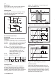
0.0
0.5
1.0
1.5
2.0
2.5
3.0
3.5
μS/cm
USP
Safety
Margin
25
50
75
100
˚C
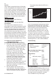
Figure 5-6. USP Safety Margin
Limitofuncompensatedconductivityasfunction
oftemperatureasdefinedforWFI.USPsafety
marginsetas20%willclosethecontactat80%
of the conductivity value at all temperatures.
Forexample,ifthetemperatureis64ºC.and
thesafetymarginisadjustedfor20%,thenthe
contactclosesat0.8x2.2μS/cm.=1.76μS/cm.
(2.2 μS/cmistheWFIlimitat64ºC).Inresistivity
mode the contact will close at an uncompensated
resistivity of 1/1.76 μS/cm.=0.568Mohm.
Recommended Commissioning settings when
monitoringWFIina>80ºCWFIinstallation.
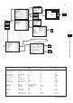
Commissioning
Measurement Set up
Measure
Conductivity only
Temp Compensation automatic
Conductivity 1 None
Error Configuration (Errors 2/3)
USPlimitexceeded Warn
Output Setup
S1 USP
USPsafetymargin 10%
S2 Alarm
Parameter Temperature
Setpoint 80C
Direction Low
Delay Time 0.2 s
Expiry Time 0 (disabled)
5-11. Input contacts
TheterminaloftheSC450Gprovidesforanin-
putcontact(seeFigure3-7).Thisinputcontact
can be used to switch the range of the outputs.
The range can be increased by 1 decade.
This is available for only mA1 output.