
User guide

13
IM 12D08N05-01E
3 INSTALLATIONANDWIRING
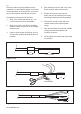
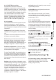
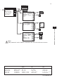
3-6-1. Sensor cable connections using junc-
tion box (BA10) and extension cable
(WF10)
Where a convenient installation is not possible
using the standard cables between sensors
and converter, a junction box and extension
cablemaybeused.TheYokogawaBA10
junctionboxandtheWF10extensioncable
should be used. These items are manufactured
to a very high standard and are necessary to
ensure that the specifications of the system
can be met. The total cable length should not
exceed 60 metres (e.g. 5 m fixed cable and 55
m extension cable).
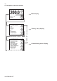
14 Overall Screen
11
12
12
13
14
14 16
15
1314141615
17
11
17
11 Red
12 Blue
13 Core 17 Screen
Brown Co-axial Cable
15 Core 16 Screen
White Co-axial cable
17 (screen)
14 (overall screen)
12 (blue)
11 (red)
13 (core)
16 (screen)
15 (core)
Co-axial cable
(white)
Co-axial cable
(brown)
11
12
13
14
15
16
17
BA10 WF10
EXA TRANSMITTER
/ CONVERTER
11
12
13
14
15
16
17
Figure 3-10. Connection of WF10 extension cable and BA10 junction box
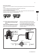
Other sensor systems
To connect other sensor systems, follow the general pattern of the terminal connections as listed
below:
11 and 12: Always used for temperature compensation resistor input.
13 and 14: Normally used for the outer electrode
15and16:Usedforinnerelectrode
In case a 4-electrode measuring system will be used, 14 and 16 should be used for the current
electrodes. Please ensure that shielded cabling will be used.
In below figure this is shown in a schematic way.
11 12
13
14 15 16
t
11 12
13
14 15 16
t