
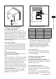
User guide

10
IM 12D08N05-01E
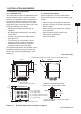
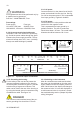
3-3-5. Grounding the housing
Forthesafetyoftheuserandtoprotectthe
instrument against interference, the housing
must always be connected to ground. This has
to be done by a large area conductor. This
cable can be fixed to the rear of the housing or
by using the internal ground connections using
abraidedwirecable.Seefigure3-8.
The minimum cross sectional area of the pro-
tective grounding wire should be 0.75 mm
2
.
3-3-6. Switching on the instrument
After all connections are made and checked,
the power can be switched on from the power
supply.MakesuretheLCDdisplaycomeson.
After a brief interval, the display will change to
the measured value. If errors are displayed or
a valid measured value is not shown, consult
the troubleshooting section (Chapter 8) before
calling Yokogawa.
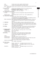
DANGER
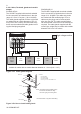
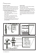
Figure 3-7. Input and output connections
63 66 65 61 22 21 12 15 16
- + - +
mA OUTPUTS
62 11 13
TEMPmA2
SHLD
CONTACT SENSOR(S)
REFER TO INSTRUCTION MANUAL FOR CONNECTIONS
SC
mA1
(+HART)
14
ELECTRODE
INNER INNEROUTER OUTER
+ -
32 31 33 42 41 43 52 51 53 72 71 73
NC C NO NC C NO NC C NO NO C NC
S1 S2 S3CONTACTS S4
250V / 5A
AC / DC
100VA / 50W
(fail-safe)
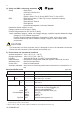
Fusereplacementshouldbeperformedonlyby
a qualified service personnel.
SeeSec.7.MAINTENANCE,Fuse
Fuse ratings:
Powersupply Fusetype
12-24VDC,10Wmax 2A/250V,Slow
100-240VAC,15VAmax 0.5A/250V,Slow
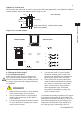
3-3-2. Access to terminal and cable entry
Terminals 1 and 2 are used for the power sup-
ply.Guidethepowercablesthroughthegland
closest to the power supply terminals. The ter-
minals will accept wires of 2.5 mm
2
(14AWG).
Always use cable finishings if possible.
WARNING
2 1
- +
DC
POWER
12-24 V /10 W
FUSE: 2A/250 VAC/T
2 1
N L
AC
POWER
FUSE: 500 mA/250 VAC/T
100-240 VAC/15 VA/ 50/60Hz
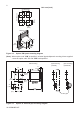
3-3-3. AC power
ConnectterminalLtothephaselineoftheAC
powerandterminalNtothezeroline.Seefig-
ure 3-8 for the power ground. This is separated
from input ground by a galvanic isolation.
3-3-4. DC power
Connect terminal 1 to the positive outlet and
terminal 2 to the negative outlet.
This is separated from input ground by a
galvanic isolation. The size of conductors
should be at least 1.25 mm
2
. The overall cable
diametershouldbebetween6&12mm.