
User guide

5
IM 12D08N05-01E
3 INSTALLATIONANDWIRING
3-1. Installation and dimensions
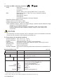
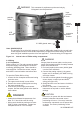
3-1-1. Installation site
The EXAxt 450 converter is weatherproof and
can be installed inside or outside. It should,
however, be installed as close as possible to
the sensor to avoid long cable runs between
sensor and converter. In any case, the cable
length should not exceed 60 metres (197 feet).
Selectaninstallationsitewhere:
• Mechanicalvibrationsandshocksare
negligible
• Norelay/powerswitchesareinthedirect
environment
• Accessispossibletothecableglands
(see figure 3-1)
• Theconverter is not mounted in direct
sunlight or severe weather conditions
• Maintenanceproceduresarepossible
(avoiding corrosive environments)
The ambient temperature and humidity of the
installation environment must be within the
limitsoftheinstrumentspecifications.(See
chapter 2).
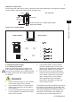
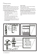
3-1-2. Mounting methods
Refer to figures 3-2 and 3-3. Note that the
EXAxt converter has universal mounting capa-
bilities:
• Panelmountingusingoptionalbrackets
• Surfacemountingonaplate(usingbolts
from the back)
• Wallmountingonabracket(forexample,
on a solid wall)
• Pipemountingusingabracketona
horizontal or vertical pipe
Sizenominal50A
3. INSTALLATION AND WIRING
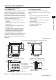
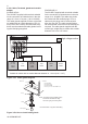
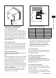
Figure 3-1. Housing dimensions and layout of glands
220(8.66")184(7.2")
72(2.8")
A
D E F
B C
A : For output signal
B : For contact input
C : For sensor cable
D : For contact output (S1 and S2)
E : For contact output (S3 and S4)
F : For power supply
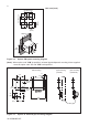
Adapter
49
(1.93")
G1/2 screw (/AFTG), 1/2 NPT screw (/ANSI)
M20 screw (/AM20)
Approx.
55(2.2")
144(5.67")
144(5.67")
20
(0.79")
20
(0.79")
121.5(4.78")
24.5(1")
Adapter for Coduit Work (optional)
(option code : / AFTG, / ANSI, / AM20)
M20 cable gland
(When shipped, not installed)
Grounding terminal (M4 screw)
Hood (Option code: /H5, some cutout on the left side cover)
Unit: mm (inch)