
User guide

IM 12D08B02-01E
2-8 Specifications
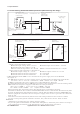
Sensor
terminals 11-16
Max. cablelength: 60 mtr.
Cable dia. : 3…12 mm.
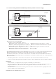
Sensor
terminals 11-16
Max. cablelength: 60 mtr.
Cable dia.: 3…12 mm.
Ùnclassified Location
FM Approved
Power Supply
(HART compatible)
Output
Supply
+
_
G
Classified Location
Unclassified Location
+
_
G
earth
earth
Intrinsically safe design
FM Class I, Div.1, Group ABCD, T4 for ambient temp. < 55°C
T6 for ambient temp. < 40°C
SC202S transmitter
+
-
Load
Resistance
Classified Location
earth
+
_
24 volts DC Nominal
Supply Voltage.
FM Approved safety barrier or
power supply
with Rint = 300 :
(HART compatible)
For electrical data:
see text below.
For electrical data:
see text below.
Intrinsically safe design
FM Class I, Div.1, Group ABCD, T4 for ambient temp. < 55°C
T6 for ambient temp. < 40°C
SC202S transmitter
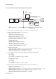
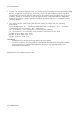
Figure 1
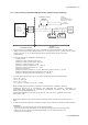
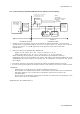
Figure 2
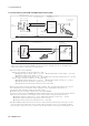
Functional
Functional
Functional
・ Electrical data of the SC202S.
- Supply circuit (terminals + and ):
Maximum input voltage Vmax = 31.5 V. Maximum input current Imax = 100 mA.
Maximum input power Pmax = 1.2 W.
Effective internal capacitance Ci = 22 nF. Effective internal inductance Li = 35 PH.
- Sensor input circuit (terminals 11 through 16) :
Maximum output voltage Vt = 14.4 V. Maximum output current It = 10 mA.
Maximum allowed external capacitance Ca = 59.36 nF.
Maximum allowed external inductance La = 340 mH.
・ If Hand Held Terminal (HHT) is not connected to the power supply lines of the SC202S
(see figure 1):
Any FM Approved barrier or power supply may be used that meets the following requirements.
Voc or Vt d 31.5 V ; Isc or It d 100 mA; Ca t 22nF + Ccable ; La t 35PH + Lcable
If HHT is connected to the power supply lines of the SC202S (see figure 2):
The Hand Held Terminal must be FM Approved. Refer to the manufacturers control drawing of the
HHT and the barrier/power supply to determine the cable parameters.
(Voc or Vt ) + VHHT d 31.5 V; (Isc or It ) + IHHT d 100 mA;
Ca t 22nF + Ccable+ CHHT ; La t 35PH + Lcable+ LHHT
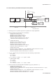
When installing this equipment, follow the manufacturer’s installation drawing.
Installation should be in accordance with ANSI/ISA RP 12.06.01 “Installation of Intrinsically Safe
Systems for Hazardous (Classified) Locations” and the National Electrical Code (ANSI/NFPA 70).
Control equipment connected to the barrier/power supply must not use or generate more than 250
Vrms or Vdc.
・ Resistance between Intrinsically Safe Ground and earth ground must be less than 1.0 Ohm.
・ In case of using cable glands in Outdoor location, they shall be UV rated or made of metal.
WARNING
- Substitution of components may impair Intrinsic Safety
- To prevent ignition of flammable or combustible atmospheres, disconnect power before servicing or
read, understand and adhere to the manufacturer’s’live maintenance procedures.
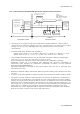
2-6. Control Drawing SC202S mA HART
®
Specification (FM Intrinsically safe design).
Application Doc. No.: IKE026-A10 P.5 to P.6