User’s Manual Model SC202G [Style: S3], SC202S [Style: S3] 2-wire Conductivity or Resistivity Transmitter IM 12D08B02-01E IM 12D08B02-01E 8th Edition
TABLE OF CONTENTS PREFACE 1. Introduction And General Description ............................................................. 1-1 1-1. Instrument check ............................................................................................ 1-1 1-2. Application ...................................................................................................... 1-3 2. general Specifications ....................................................................................... 2-1 2-1.
4. Operation; Display Functions And Setting ...................................................... 4-1 4-1. Operator interface ........................................................................................... 4-1 4-2. Explanation of operating keys......................................................................... 4-2 4-3. Setting passcodes .......................................................................................... 4-3 4-3-1. Passcode protection ................................
11. Appendix 1 ........................................................................................................ 1-1 11-1. User setting for non-linear output table (code 31and 35)............................... 1-1 11-2. User entered matrix data (code 23 to 28)...................................................... 1-1 11-3. Matrix data table (user selectable in code 22)............................................... 1-2 11-4. Sensor Selection...........................................................
PREFACE DANGER Electric discharge The EXA analyzer contains devices that can be damaged by electrostatic discharge. When servicing this equipment, please observe proper procedures to prevent such damage. Replacement components should be shipped in conductive packaging. Repair work should be done at grounded workstations using grounded soldering irons and wrist straps to avoid electrostatic discharge.
The following safety symbols are used on the product as well as in this manual. DANGER DANGER This symbol indicates that an operator must follow the instructions laid out in this manual in order to avoid the risks, for the human body, of injury, electric shock, or fatalities. The manual describes what special care the operator must take to avoid such risks.
ATEX Documentation This procedure is only applicable to the countries in European Union. GB All instruction manuals for ATEX Ex related products are available in English, German and French. Should you require Ex related instructions in your local language, you are to contact your nearest Yokogawa office or representative. DK Alle brugervejledninger for produkter relateret til ATEX Ex er tilgængelige på engelsk, tysk og fransk.
SK PL CZ SLO LT H BG LV EST RO M IM 12D08B02-01E
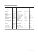
CONFIGURATION CHECKLIST FOR SC202 Primary choices Measurement default Conductivity alternatives Resistivity max. 1999 mS/cm reference on page 5.8- 5.9 menu SC 01 Range 0-1000 μS/cm 5.3 “range” Temperature unit Celsius Fahrenheit 5.10- 5.11 SC 11 Cell constant 0.1 /cm any value between 0.08 and 50 5.8-5.9, 6.1- 6.3 SC 03 Sensor type 2-electrode 4- electrode 5.8- 5.9 SC 02 Temperature compensator Pt1000 Ni100, Pt100, 8k55, Pb36 5.10-5.11 SC 10 enabled disable HART(R), PH201*B 5.
Introduction 1-1 1. INTRODUCTION AND GENERAL DESCRIPTION The Yokogawa EXA 202 is a 2-wire transmitter designed for industrial process monitoring, measurement and control applications. This user’s manual contains the information needed to install, set up, operate and maintain the unit correctly. This manual also includes a basic troubleshooting guide to answer typical user questions. Yokogawa can not be responsible for the performance of the EXA analyzer if these instructions are not followed. 1-1.
1-2 Introduction CONDUCTIVITY TRANSMITTER MODEL SUFFIX SC202S-F MODEL SUFFIX SUPPLY FISCO 17.5VDC or 24VDC CONDUCTIVITY TRANSMITTER 17.5VDC or 24VDC /250mA/1.2W II 1G /380mA/5.32W FF-TYPE111 or 511 Li=0 μH, Ci=220pF OUTPUT PROFIBUS-PA Li=0 μH, Ci=220pF AMB.TEMP. -10 55°C AMB.TEMP. -10 55°C STYLE No.
Introduction 1-3 1-2. Application The EXA transmitter is intended to be used for continuous on-line measurement in industrial installations. The unit combines simple operation and microprocessor-based performance with advanced selfdiagnostics and enhanced communications capability to meet the most advanced requirements. The measurement can be used as part of an automated process control system.
1-4 Introduction IM 12D08B02-01E
Specifications 2-1 2. GENERAL SPECIFICATIONS C. Input ranges - Conductivity : Minimum : 0 μS/cm Maximum : 200 mS x (Cell constant) (overrange 1999 mS / cm). - Resistivity : Minimum : 0.005 kΩ/ (Cell constant) Maximum : 999 MΩ x cm - Temperature Pt1000 : -20 to +250 °C (0 to 500 °F) Pt100 and Ni100 : -20 to +200 °C (0 to 400 °F) 8K55 NTC : -10 to +120 °C (10 to 250 °F) PB36 NTC : -20 to +120 °C (0 to 250 °F) mA D. Output Span - Conductivity : - min 0.01μS/cm : - max. 1999 mS/cm.
2-2 Specifications 2-2. Operating specifications A. Performance (under reference conditions with sensor simulation) Conductivity (2 μS x K cm-1 to 200 mS x K cm-1) - Accuracy : ±0.5% F.S. Conductivity (1 μS x K cm-1 to 2 μS x K cm-1) - Accuracy : ±1% F.S. Resistivity (0.005kΩ/ K cm-1 to 0.5MΩ/ K cm-1) - Accuracy : ±0.5% F.S. Resistivity (0.5MΩ/ K cm-1 to 1MΩ/ K cm-1) - Accuracy : ±1% F.S. Temperature (Pt1000Ω, PB36 NTC, Ni100) - Accuracy : ±0.3°C Temperature (Pt100Ω, 8.55kΩ NTC) mA - Accuracy : ±0.
Specifications 2-3 Item Item CENELEC ATEX Entity CENELEC ATEX FISCO CENELEC ATEX Description CENELEC ATEX (KEMA) Intrinsically safe Approval Applicable standard: EN60079-0, EN50020 EN60079-26 Certificate: KEMA 07ATEX0050 X Ex ia IIC, Group: II, Category: 1G Temp. Class: T4, Amb. Temp.: -10 to 55°C Ui=24 V, Ii=250 mA, Pi=1.
2-4 Specifications GB3836.13-1997 "Electrical apparatus for explosive gas atmospheres Part 13: Repair and overhaul for apparatus used in explosive gas atmospheres". GB3836.15-2000 "Electrical apparatus for explosive gas atmospheres- Part 15: Electrical installations in hazardous area (other than mines)" . GB3836.16-2006 "Electrical apparatus for explosive gas atmospheres- Part 16: lnspection and maintenance of electrical installation (other than mines)". mA mA-HART® communication A.
H. Function blocks: 3 x AI, Transducer, Resource I. Files: Actual file can be downloaded from our homepage J. Configuration: locally with 6 keys Specifications 2-5 National Instruments: NI-FBUS configurator L. Hardware: F-BUS interfaces from National Instruments (AT-FBUS, PCMIA-FBUS) M. Other control systems: YOKOGAWA PRM, DTM K. Software: 2-3. Model and suffix codes 1.
2-6 Specifications 2-4. Control Drawing SC202S mA HART® Specification (IECEx) Intrinsically safe design IEC Ex standard Ex ia IIC : T4 for ambient temp. < 55°C T6 for ambient temp. < 40°C C ertificate nr. IEC Ex KEM 06.0053X SC 202S (C onductivity/R esistivity-transmitter) Ex ia or ib C ertified safety barrier or pow er w ith R int=300 : (HAR T compatible) 24 volts D C N ominal Supply V oltage. + + _ SENSO R (S) term inals 11-16 _ U o = 31.
Specifications 2-7 2-5. Control Drawing SC202S mA HART® Specification (ATEX) Intrinsically safe design CEN ELEC standard EEx ia IIC : T4 for ambient temp. < 55°C T6 for ambient temp. < 40°C C ertificate nr. KEM A 06ATEX 0220 X SC 202S (C onductivity/Resistivity-transmitter) EEx ia or ib C ertified safety barrier or pow er w ith R int=300 : (HAR T compatible) 24 volts D C N ominal Supply V oltage.
2-8 Specifications 2-6. Control Drawing SC202S mA HART® Specification (FM Intrinsically safe design). Intrinsically safe design FM Class I, Div.1, Group ABCD, T4 for ambient temp. < 55°C T6 for ambient temp. < 40°C SC202S transmitter FM Approved safety barrier or power supply with Rint = 300 : (HART compatible) 24 volts DC Nominal Supply Voltage. + + _ - G Sensor For electrical data: see text below. terminals 11-16 Max. cablelength: 60 mtr. Cable dia. : 3…12 mm.
Specifications 2-9 2-7. Control Drawing SC202S mA HART® Specification (FM Non-incendive design) N o n in c e n d iv e d e s ig n F M C la s s I, D iv .2 , G ro u p A B C D , T 4 fo r a m b ie n t te m p . < 5 5 ° C T 6 fo r a m b ie n t te m p . < 4 0 ° C F M A p p ro v e d p o w e r s u p p ly V o c ≦ 3 1 .5 V D C S C 2 0 2 S tra n s m itte r + + _ - G S enso r F o r e le c t r ic a l d a t a : s e e t e x t b e lo w . te rm in a ls 1 1 -1 6 M a x . c a b le le n g th : 6 0 m tr. C a b le d ia .
2-10 Specifications 2-8. Control Drawing of SC202S mA HART® Specification (CSA) Intrinsically safe d esign C S A E x ia C lass1, D iv.1, G ro up A B C D , SC 202 S T 4 fo r ambient tem p. < 55°C T 6 fo r am bient tem p. < 40°C transm itter C S A certified safety barrier or pow er supp ly w ith R int= 300 : (H A R T com patible) 24 volts D C N om inal S upply V oltage. + + _ Sen sor term in als 1 1 -1 6 _ S uitable values are: G V m ax = 31.
Specifications 2-11 2-9. Control Drawing of SC202S FF/PB Specification (IECEx) Ex ia IIC T4 for ambient temp. d 55 qC Ui = 24 V or Ui = 17,5 V Ii = 250 mA Ii = 380 mA Pi = 1,2 W Pi = 5,32 W SC202S-F or SC202S-P + Safe area Apparatus + - I.S. interface Sensor Connections - I.S. certified Term inator I.S. certified Term inator + - Transm itter Safe area + - Transm itter Zone 0 or 1 Hazardous area x Sensor(s) are of a passive type to be regarded as 'simple apparatus'.
2-12 Specifications 2-10. Control Drawing of SC202S FF/PB Specification (ATEX) Ex ia IIC T4 for ambient temp. d 55 qC Ui = 24 V or Ui = 17,5 V Ii = 250 mA Ii = 380 mA Pi = 1,2 W Pi = 5,32 W SC202S-F or SC202S-P + Safe area Apparatus + - I.S. interface Sensor Connections - I.S. certified Terminator I.S. certified Terminator + - Transmitter Safe area + - Transmitter Zone 0 or 1 Hazardous area x Sensor(s) are of a passive type to be regarded as 'simple apparatus'.
Specifications 2-13 2-11. Control Drawing of SC202S FF/PB Specification (FM Intrinsically safe Entity) FM Class I, DIV. 1, Group ABCD T4 for ambient temp. d 55 qC Sensor Connections Max. cablelength: 60 mtr. Cable dia. : 3…12 mm. SC202S-F or SC202S-P + FM Approved barrier Voc (Vt) d 24 V Ioc (It) d 250 mA Poc (Pt) d 1.2 W Ca t 220pF+ Ccable La t 0 H + Lcable + - Sensor Connections - I.S. certified Terminator I.S.
2-14 Specifications x The cable used to interconnect the devices needs to comply with the following parameters: Loop resistance R’: 15 … 150 Ω/km; Inductance per unit length L’: 0,4 … 1 mH/km Capacitance per unit length C’: 80 … 200 nF/km (C’ = C’ line/line + 0,5 C’ line/screen if both line are floating) (C’ = C’ line/line + C’ line/screen if the screen is connected to one line) Length of spur cable: max. 30 m Length of trunk cable: max. 1 km Length of splice : max.
Specifications 2-15 2-12. Control Drawing of SC202S FF/PB Specification (FM Intrinsically safe FISCO) FM Class I, DIV. 1, Group ABCD T4 for ambient temp. d 55 qC Sensor Connections Max. cablelength: 60 mtr. Cable dia. : 3…12 mm. Sensor Connections SC202S-F or SC202S-P + FM Approved FISCO barrier Voc (Vt) d17,5 V Ioc (It) d380 mA Poc (Pt) d5,32 W + - - FM Approved Terminator R = 90..100Ω C = 0..2,2 μF FM Approved Terminator R = 90..100Ω C = 0..
2-16 Specifications x In each I.S. Fieldbus segment only one active source, normally the FM Approved FISCO barrier, is allowed to provide the necessary power for the Fieldbus system. All other equipment connected to the bus cable has to be passive (not providing energy to the system), except to a leakage current of 50μA for each connected device. Seperately powered equipment needs a galvanic isolation to insure that the I.S. Fieldbus circuit remains passive.
Specifications 2-17 2-13. Control Drawing of SC202S FF/PB Specification (FM Non-incendive Entity) FM Class I, DIV. 2, Group ABCD T4 for ambient temp. d 55 qC T6 for ambient temp. d 40 qC Sensor Connections Max. cablelength: 60 mtr. Cable dia.: 3…12 mm. Sensor Connections SC202S-B or SC202S-D FM Approved Power Supply Voc d 32 VDC + - + - FM Approved Terminator R = 90..100Ω C = 0..2,2 μF FM Approved Terminator R = 90..100Ω C = 0..
2-18 Specifications 2-14. Control Drawing of SC202S FF/PB Specification (FM Non-incendive FNICO) FM Class I, DIV. 2, Group ABCD T4 for ambient temp. d 55 qC T6 for ambient temp. d 40 qC Sensor Connections Max. cablelength: 60 mtr. Cable dia.: 3…12 mm. Sensor Connections SC202S-B or SC202S-D + FM Approved Power Supply Voc d 32 VDC - FM Approved Terminator R = 90..100Ω C = 0..2,2 μF + - FM Approved Terminator R = 90..100Ω C = 0..
Specifications 2-19 2-15. Control Drawing of SC202S FF/PB Specification (CSA) CSA Ex ia Class I, DIV. 1, Group ABCD T4 for ambient temp. d 55 qC Ui = 24 V Ii = 250 mA Pi = 1,2 W or Ui = 17,5 V Ii = 380 mA Pi = 5,32 W SC202S-F or SC202S-P + Safe area Apparatus + - I.S. interface Sensor Connections - I.S. certified Terminator I.S.
2-20 Specifications IM 12D08B02-01E
Installation and wiring 3-1 3. INSTALLATION AND WIRING 3-1. Installation and dimensions 3-1-1. Installation site The EXA transmitter is weatherproof and can be installed inside or outside. It should, however, be installed as close as possible to the sensor to avoid long cable runs between sensor and transmitter. In any case, the cable length should not exceed 60 meters (200 feet).
3-2 Installation and wiring Unit: mm (inch) 18.5 (0.72) +1 0 +1 0 SPACING PANEL CUTOUT PANEL CUTOUT 3.5 (0.14) Fig. 3-2b. Panel mounting using two (2) self-tapping screws Unit: mm (inch) Pipe mounting (Vertical) 56 (2.20) Pipe mounting (Horizontal) 2-Ø6.5 (0.26) 200 (7.87) 4-Ø10 (0.4) 77 (3) 115 70 (4.5) (2.75) Nominal 50 A (O.D. Ø60.5 mm) (2 inch pipe) 4.eps Figure 3-3. Wall and pipe mounting diagram Figure 3-4.
Installation and wiring 3-3 mA 3-2. Preparation Refer to figure 3-4. The power/output connections and the sensor connections should be made in accordance with the diagram on page 3-6. The terminals are of a plug in style for ease of mounting. To 1. 2. 3. 4. open the EXA 202 for wiring: Loosen the four frontplate screws and remove the cover. The terminal strip is now visible. Connect the power supply. Use the gland on the left for this cable. Connect the sensor input, using the gland on the right (see fig.
3-4 Installation and wiring COMPUTER HAND HELD COMMUNICATOR HOLD FAIL YES NO ENT NO MODE > YES MODE MEASURE AUT.CAL MAN.CAL DISPLAY TEMP HOLD > ENT YOKOGAWA OUTPUT/SUPPLY INPUT SENSORS CURRENT OUTPUT 2,5 or 10 m DISTRIBUTOR 0 12 100 180 RECORDER Safety Barrier SC202S only Figure 3-6. System configuration 3-3. Wiring of sensors 3-3-1. General precautions Generally, transmission of signals from SC sensors is at a low voltage and current level.
Installation and wiring 3-5 3-3-3. Installation in: Hazardous Area-Non-Incendive The SC202S-N may be installed in a Category 3/ Zone 2/ Div.2 area without the use of safety barriers. Maximum permissible supply voltage 31.5V. 3-4. Wiring of power supply 3-4-1. General precautions WARNING Do not activate the power supply yet. First make sure that the DC-power supply is according to the specifications given.
3-6 Installation and wiring 3-5. Sensor wiring Refer to figure 3-9, which includes drawings that outline sensor wiring. For the SC4AJ, SC8SG and SC210G sensors, see Appendix 2. The EXA SC202 can be used with a wide range of commercially available sensor types if provided with shielded cables, both from Yokogawa and other manufacturers. The sensor systems from Yokogawa fall into two categories, the ones that use fixed cables and the ones with separate cables.
Installation and wiring 3-7 3-6. Other sensor systems To connect other sensor systems, follow the general pattern of the terminal connections as listed below: 11 and 12 : Always used for temperature compensation resistor input. 13 and 14 : Normally used for the outer electrode 15 and 16 : Used for inner electrode In case a 4-electrode measuring system will be used, 14 and 16 should be used for the current electrodes. Please ensure that shielded cabling will be used.
3-8 Installation and wiring TRANSMITTER/ CONVERTER 16 15 15 16 17 17 13 12 11 13 14 14 14 14 11 12 15 Core 16 Screen White Co-axial cable 11 14 Overall Screen 12 WF10 Cable 13 Core 17 Screen Brown Co-axial Cable 17 13 15 11 Red 16 12 Blue 14 Thermistor (Temperature sensor) Secondary Coil Primary Coil Ground (Shield) Red C E B Brown A Overall shield White Screen D Blue Fig. 3-12.
Installation and wiring 3-9 Extension cable may be purchased in bulk quantities, cut to length. Then it is necessary to terminate the cable as shown below. Termination procedure for WF10 cable. 1. Slide 3 cm of heat shrink tube (9 x 1.5) over the cable end to be terminated. 2. Strip 9 cm of the outer (black) insulating material, taking care not to cut or damage internal cores. 3 cm 9 cm heat shrink remove insulation Fig. 3-13a. 3.
Operation 4-1 4. OPERATION; DISPLAY FUNCTIONS AND SETTING 4-1. Operator interface This section provides an overview of the operation of the EXA operator interface. The basic procedures for obtaining access to the three levels of operation are described briefly. For a step-by-step guide to data entry, refer to the relevant section of this user’s manual. Figure 4-1 shows the EXA operator interface. LEVEL 1: Maintenance These functions are accessible by pushbutton through a flexible front cover window.
4-2 Operation Fail flag Output hold flag Menu pointer flags Units HOLD FAIL MODE Main display Message display YES NO ENT Key prompt flags Selection keys YES : Accept setting NO : Change setting Adjustment keys > : Choose digit to adjust ^ : Adjust digit ENT : Confirm change YES NO MEASURE CAL DISPLAY HOLD MODE Commissioning function menu OUTPUT SET HOLD TEMP.
Operation 4-3 4-3. Setting passcodes 4-3-1. Passcode protection In Service Code 52, EXA users can set passcode protection for each one of the three operating levels, or for any one or two of the three levels. This procedure should be completed after the initial commissioning (setup) of the instrument. The passcodes should then be recorded safely for future reference.
4-4 Operation 4-5. Display functions Sequence for resistivity function is similar to this conductivity example. Display Functions (Sequence for resistivity function equals this conductivity example). μS / c m Actual cell constant YES NO NO μS/cm μS / c m Reference temperature MODE DISP.1 or DISP.
Parameter setting 5-1 5. PARAMETER SETTING 5-1. Maintenance mode 5-1-1. Introduction Standard operation of the EXA instrument involves use of the Maintenance (or operating) mode to set up some of the parameters. Access to the maintenance mode is available via the six keys that can be pressed through the flexible window in the instrument front cover. Press the “MODE” key once to enter this dialog mode.
5-2 Parameter setting 5-2. Commissioning mode 5-2-1. Introduction In order to obtain peak performance from the EXA SC202, you must set it up for each custom application. *OUTP : mA output is set as default to 0-1 mS/cm or 0-19.99 MΩ·cm. For enhanced resolution in more stable measuring processes, it may be desirable to select for example 5-10 μS/cm range. mA *HOLD : The EXA SC202 transmitter has the ability to “HOLD” the output during maintenance periods.
Parameter setting 5-3 5-2-2. Range MODE MEASURE CAL DISPLAY HOLD YES NO OUTPUT SET HOLD TEMP.
5-4 Parameter setting mA 5-2-3. HOLD MODE MEASURE CAL DISPLAY HOLD OUTPUT SET HOLD TEMP. SERVICE HOLD ENT YES NO HOLD NO ENT YES NO YES NO YES HOLD NO NO YES ENT YES NO NO YES NO Set HOLD "fixed value" YES HOLD HOLD NO YES NO NO YES NO NO YES IM 12D08B02-01E YES NO HOLD active last measured value.
Parameter setting 5-5 5-2-4. Temperature compensation 1. Why temperature compensation? The conductivity of a solution is very dependent on temperature. Typically for every 1 °C change in temperature the solution conductivity will change by approximately 2 %. The effect of temperature varies from one solution to another and is determined by several factors like solution composition, concentration and temperature range.
5-6 Parameter setting 5-2-5. Temperature compensation selection MODE MEASURE CAL DISPLAY HOLD OUTPUT SET HOLD TEMP. SERVICE > After briefly displaying *WAIT* it will be possible to adjust the display reading to the correct value using > ENT keys. YES μS/cm mA YES NO YES NO ENT NO NO ENT YES NO mA YES NO NO NO YES YES NO YES NO YES YES NO NO YES NO NO IM 12D08B02-01E NO YES Briefly *WAIT* TEMP.1 or TEMP.
Parameter setting 5-7 5-2-6. Service code The figure below shows a typical button sequence to change a setting within the service menu. The specific settings are listed in numerical sequence on the following pages. On the page facing the setting tables are concise explanations of the purpose of the service codes. MODE MEASURE CAL DISPLAY HOLD OUTPUT SET HOLD TEMP. SERVICE After changing the parameter, the instrument first goes into reset to load the parameter specific default values.
5-8 Parameter setting 5-3. Service Codes Don't set or input service code numbers other than the code numbers defined in this manual. Setting an undefined service code may make the transmitter malfunction. When an undefined service code is input by some accident, push the MODE key and escape from the service level. 5-3-1. Parameter specific functions Code 01 *SC.RES Choose the required parameter, either conductivity or resistivity.
Parameter setting 5-9 Code Display Function Parameter specific functions 01 *SC.RES Function detail Select main parameter Conductivity 03 *4.ELEC 0.10xC Select 2/4-EL system Set cell constant Y 0 Z Default values 0 Cond. 0 2-El. Press NO to step through choice of 1.000 cm-1 multiplying factors on the second display. 0.10xC Resistivity 02 X 1 2-Electrode measurement system 0 4-Electrode measurement system 1 0.10xC 1.00xC 10.0xC 100.xC 0.
5-10 Parameter setting 5-3-2. Temperature measuring functions Code 10 *T.SENS Selection of the temperature compensation sensor. The default selection is the Pt1000 Ohm sensor, which gives excellent precision with the two wire connections used. The other options give the flexibility to use a very wide range of other conductivity/resistivity sensors. Code 11 *T.UNIT Celsius or Fahrenheit temperature scales can be selected to suit user preference. Code 12 *T.
Parameter setting 5-11 Code Display Function Temperature measuring functions 10 11 12 *T.SENS *T.UNIT *T.ADJ Temperature sensor Display in °C or °F Function detail Pt1000Ω X 0 Ni100Ω 1 Pb36 (PB36NTC) 2 Pt100Ω 3 8k55 (8.55kΩNTC) 4 °C 0 °F 1 Calibrate temperature Adjust reading to allow for cable Y Z Default values 0 Pt1000 0 °C None resistance.
5-12 Parameter setting 5-4. Temperature compensation functions Code 20 *T.R.°C Choose a temperature to which the measured conductivity (or resistivity) value must be compensated. Normally 25°C is used, therefore this temperature is chosen as default value. Limitations for this setting are: 0 to 100 °C. If *T.UNIT in code 11 is set to °F, default value is 77°F and the limitations are 32 - 212°F. Code 21 *T.C.
Parameter setting 5-13 Code Display Function Temperature compensation functions Function detail X Y Z Default values 20 *T.R.°C Set reference temp. Use >, ^, ENT keys to set value 25 °C 21 *T.C.1 Set temp. coef. 1 Adjust compensation factor 2.1 % if set to TC in section 5-2-5. per °C Set value with >, ^, ENT keys *T.C.2 Set temp. coef. 2 Adjust compensation factor 2.1 % if set to TC in section 5-2-5.
5-14 Parameter setting mA 5-5. mA output functions Code 31 *OUTP.F For the SC202 the output may be chosen as linear to input, or configured in a 21 point table to a particular linearization. Enable the table setup in code 31, and configure the table in code 35. Code 32 *BURN Diagnostic error messages can signal a problem by sending the output signals upscale or downscale (21 mA or 3.6 mA when HART or distributor comm. is non-used, 3.9 mA when HART or distributor comm. is used).
Parameter setting 5-15 mA Code Display mA Outputs 30 31 *OUTP.F Function 32 *BURN Burn function *TABLE *0% *5% *10% ... ... *95% *100% Output table for mA 33, 34 35 36-39 mA output functions Function detail X Not used Linear Table No burnout Burnout downscale Burnout upscale Pulse burnout Not used 0 1 0 1 2 3 Y Z Default values 0 Linear 0 No Burn. Linearization table for mA in 5% steps.
5-16 Parameter setting 5-6. User interface Code 50 *RET. When Auto return is enabled, the transmitter reverts to the measuring mode from anywhere in the configuration menus, when no button is pressed during the set time interval of 10 minutes. Code 52 *PASS Passcodes can be set on any or all of the access levels, to restrict access to the instrument configuration. Code 53 *Err01 to 13 Error message configuration. Two different types of failure mode can be set.
Parameter setting 5-17 Code Display User interface 50 *RET. 51 52 53 54 *PASS *Err.01 *Err.05 *Err.06 *Err.07 *Err.08 *Err.13 *E5.
5-18 Parameter setting 5-7. Communication setup mA Code 60 *COMM. *ADDR. The settings should be adjusted to suit the communicating device connected to the output. The communication can be set to HART® or to PH201*B distributor (see Appendix 2). Select address 00 for point to point communication with 4-20mA transmission. Addresses 01 to 15 are used in multi-drop configuration (fixed 4mA output).
Parameter setting 5-19 mA mA Code Display Communication 60 *COMM. 61 62 63-69 *ADDR.
Calibration 6-1 6. CALIBRATION 6-1 When is calibration necessary? Calibration of conductivity/resistivity instruments is normally not required, since Yokogawa delivers a wide range of sensors, which are factory calibrated traceable to NIST standards. The cell constant values are normally indicated on the top of the sensor or on the integral cable. These values can be entered directly in service code 03 (section 5-3-1).
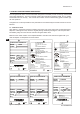
6-2 Calibration 6-2. Calibration procedure Press the MODE key. The legend CALIB appears, and the YES/NO key prompt flags flash. MODE MEASURE CAL DISPLAY HOLD YES NO MODE ENT MODE YES NO YES YES NO Put the sensor in standard solution. Press YES. ENT > After the indication is stable, set the value using the >, , ENT key. ENT > Select the flashing digit with the > key. Increase its value by pressing the key When the correct value is displayed, press ENT to enter the change.
Calibration 6-3 6-3. Calibration with HOLD active Press the MODE key. The legend CALIB appears, and the YES/NO key prompt flags flash. MODE MEASURE CAL DISPLAY HOLD YES NO MODE ENT MODE HOLD YES NO YES HOLD HOLD YES NO HOLD Put the sensor in standard solution. Press YES. ENT HOLD After the indication is stable, set the value ENT Select the flashing digit with the > key. Increase its value by pressing the key When the correct value is displayed, press ENT to enter the change.
Maintenance 7-1 7. MAINTENANCE 7-1. Periodic maintenance for the EXA 202 transmitter The EXA202 transmitter requires very little periodic maintenance. The housing is sealed to IP65 (NEMA 4X) standards, and remains closed in normal operation. Users are required only to make sure the front window is kept clean in order to permit a clear view of the display and allow proper operation of the pushbuttons. If the window becomes soiled, clean it using a soft damp cloth or soft tissue.
Troubleshooting 8-1 8. TROUBLESHOOTING The EXA SC202 is a microprocessor-based analyzer that performs continuous self-diagnostics to verify that it is working correctly. Error messages resulting from faults in the microprocessor systems itself are few. Incorrect programming by the user can be corrected according to the limits set in the following text. In addition, the EXA SC202 also checks the sensor to establish whether it is still functioning within specified limits.
8-2 Troubleshooting The following error message table gives a list of possible problems that can be indicated by the EXA. Table 8-1. Error Codes Code Error description Possible cause Suggested remedy E1 Polarization detected on cell E2 Temperature coefficient out of limits (0-3.
USP 9-1 9. USP WATER PURITY MONITORING 9-1. What is USP ? USP stands for United States Pharmacopeia and it is responsible for issuing guidelines for the pharmaceutical industry. Implementing these guidelines is highly recommended for companies wishing to market drugs in the US. This means that USP is important for pharmaceutical companies worldwide. USP recently issued: - USP - recommendations for conductivity measurement.
9-2 USP 9-4. Setting up SC202 for USP First enable USP in service code 57. Change the setting from 0 (default) to 1 (enabled). This activates uncompensated conductivity in the display menu. The E13 feature is also enabled. For E13 the FAIL flag is triggered when the uncompensated conductivity exceeds the relevant value in the graph. Conductivity limit as a function of Temperature 3,5 microSiemens/cm 3 2,5 2 1,5 1 0,5 0 0 25 50 Temperature in °C Fig. 9-1.
Spare Parts 10-1 10. SPARE PARTS See Customer Maintenance Parts List.
Appendix 1-1 11. APPENDIX 1 mA 11-1. User setting for non-linear output table (code 31and 35) Output signal value % mA Output 4-20 000 00.4 005 04.8 010 05.6 015 06.4 020 07.2 025 00.8 030 08.8 035 09.6 040 10.4 045 11.2 050 0.12 055 12.8 060 13.6 065 14.4 070 15.2 075 0.16 080 16.8 085 17.6 090 18.4 095 19.2 100 20.0 11-2. User entered matrix data (code 23 to 28) Medium: Code 23 Code 24 Code 25 Code 26 Code 27 Code 28 Temperature Solution 1 Solution 2 Solution 3 Solution 4 Solution 5 T1...
1-2 Appendix 11-3. Matrix data table (user selectable in code 22) Matrix, Solution HCL-p (cation) selection 1 Ammonia-p selection 2 Morpholine-p selection 3 Hydrochloric Acid selection 4 Sodium Hydroxide selection 5 IM 12D08B02-01E Temp (°C) 0 10 20 30 40 50 60 70 80 Data 1 0 ppb 0.0116 μS 0.0230 μS 0.0419 μS 0.0710 μS 0.1135 μS 0.173 μS 0.251 μS 0.350 μS 0.471 μS Data 2 4 ppb 0.0228 μS 0.0352 μS 0.0550 μS 0.085 μS 0.129 μS 0.190 μS 0.271 μS 0.375 μS 0.502 μS Data 3 10 ppb 0.0472 μS 0.0631 μS 0.
Appendix 1-3 11-4. Sensor Selection 11-4-1. General The inputs of the EXA transmitter are freely programmable for ease of installation. Standard 2-electrode type sensors with a cell constant of 0.100/cm and a Pt1000 temperature sensor, need no special programming. The EXA indicates a fault with a signal in the display field if there is a mismatch of sensors in the connection. 11-4-2. Sensor selection The EXA SC202 is pre/programmed to accept standard 2-electrode sensors with a Pt1000 temperature sensor.
1-4 Appendix 11-6. User setting table mA FUNCTION SETTING DEFAULTS Parameter specific functions 01 *SC.RES 0 SC 02 *4.ELEC 0 2-Elec. 03 *0.10xC 0.10xC Factor 1.000 /cm 04 *AIR 05 *POL.CK 1 On Temperature measuring functions 10 *T.SENS 0 Pt1000 11 *T.UNIT 0 °C 12 *T.ADJ None Temperature compensation functions 20 *T.R.°C 25 °C 21 *T.C.1 2.1 %/°C *T.C.2 2.1 %/°C 22 *MATRX None, see 5-2-5 23 *T1°C T. range See sep. table, 11-2 24 *L1xT1 Cond. C1 See sep. table, 11-2 25 *L2xT1 Cond. C2 See sep.
Appendix 1-5 User 50 52 53 54 FUNCTION Interface *RET *PASS *Err.01 *Err.05 *Err.06 *Err.07 *Err.08 *Err.13 *E5.LIM *E6.LIM 55 56 mA mA *0 % 100% *DISP SETTING DEFAULTS 1 0.0.0 1 1 1 1 1 0 250 (0.004) 1.000 (1.0) 0 100.0 0 (2) 0 57 *USP Communication 60 *COMM. 1.0 *ADDR. 00 61 *HOUR 62 *ERASE General 70 *LOAD Test and setup mode 80 *TEST USER SETTINGS On all off hard fail hard fail hard fail hard fail hard fail soft fail mS kΩ μS MΩ Off Auto ranging (SC) (xx.xxMΩ·cm) (RES) Off On/write ena.
1-6 Appendix 11-7.
Appendix 1-7 mA 11-8. Device Description (DD) menu structure The Device Description (DD) is available from Yokogawa or the HART foundation. An example is shown below of the ON LINE menu structure. This manual makes no attempt to explain the operation of the Hand Held Terminal (HHT). For detailed operating instructions, refer to the HHT user’s manual and the on-line help structure. For menu structure of HHT 375, see next page. Level 1 menu Level 2 menu Process variab.
1-8 Appendix Menu structure for HHT 375 shown below. ON LINE MENU Level 1 menu 1. Device setup 2. PV 3. AO1 4. LRV 5. URV 1. Process variables Note: “2. PV” means Primary value “3. AO1” means Analog output “4. LRV” means Lower rangeval “5. URV” means Upper rangeval 2. Diag/Service Level 2 menu 1. PV 2. Uncomp 3. Temp 4. PV % rnge 1. Status 2. Hold 3. Logbook 4. Loop test 3. Basic setup 4. Detailed setup 5. Review 1. Tag 2.
Appendix 2-1 12. APPENDIX 2 12-1. Preface Feasible combinations of the SC202G conductivity transmitters with different styles of the PH201G distributor are listed in the table below. The distributor has the usual distributor functions (supply power to transmitter, receive current output from transmitter, and provide analog output) as well as contact output functions (maintenance, wash and fail status signals).
2-2 Appendix 12-2. Wiring diagrams 1.
Appendix 2-3 Cables, terminals and glands The SC202 is equipped with terminals suitable for the connection of finished cables in the O.D. range: 6 to 12 mm. The glands will form a tight seal on cables with an outside diameter in the range of 6 to 12 mm. Requirement of connecting with external instruments shown below.
2-4 Appendix 12-3. Sensor wiring Refer to figure 12-1, which includes drawings that outline sensor wiring. The EXA SC202 can be used with a wide range of commercially available sensor types if provided with shielded cables, both from Yokogawa and other manufacturers. The sensor systems from Yokogawa fall into two categories, the ones that use fixed cables and the ones with separate cables.
Appendix 2-5 12-4. Supplement of parameter setting 12-4-1. Set cell constant (service code 03) Code 3 *0.10xC First select a multiplying factor, and then set the constant in consideration of this factor. The position of the decimal point can be selected after the first digit has been set (when the decimal point is flashing). *How to enter the cell constant (1) In the case that the only cell constant is mentioned on the text plate of the sensor (SC211G, SC8SG, SC4AJ). How to enter the cell constant of 0.
2-6 Appendix 12-4-4. Error setting (service code 53) Code 53 *Err01 to 13 Error message configuration: Two different types of failure mode namely, Hard fail and Soft fail can be set. Hard fail gives a steady FAIL flag in the display. When the distributor PH201G (Style B) is used and its communication is enabled in Service Code 60, the fail contact of PH201G (Style B) is closed. A fail signal is transmitted on the mA output when enabled in code 32. Soft fail gives a flashing FAIL flag in the display.
Appendix 3-1 13. APPENDIX 3 QUALITY INSPECTION 13-1. SC202G 2-Wire Conductivity Transmitter Quality Inspection Standards 1. SC202G, SC202SJ 2-Wire Conductivity Transmitter Scope This inspection standard applies to the SC202/SC202SJ 2-Wire Conductivity Transmitter. 2. Inspection Items 2.1 2.2 2.3 2.4 3. 3.
3-2 Appendix 2/3 (9) After the test at 20 mA, press the [ENT] key twice. Table 1 Current output (mA) 4.0 12.0 20.0 3.3 Current output (mA DC) 4 ±0.02 12 ±0.02 20 ±0.02 Temperature Indication Check (1) Check that the temperature sensor type indicated on the message display is “Pt1000.” (2) Change the value of the decade resistance box 1 (temperature) as shown in Table 2 and check the data display. The temperature value on the data display must be within the range shown in Table 2.
Appendix 3-3 3/3 SC202G, SC202SJ + SUPPLY G SENSOR 11 12 13 14 15 16 100 : Note 1 + DC Milliammeter - + DC source 24V DC Note 1: Ground Decade Box 1 Decade Box 2 Cable connected to sensor input should be conductivity detector cable of length 2.1 ±0.1 m. Connect pins 13 and 14, also 15 and 16, to Decade box 2 terminals. Use shielded cable, and connect shield to pin 14.
3-4 Appendix IM 12D08B02-01E
Appendix 3-5 13-2. SC202S 2-Wire Conductivity Transmitter Quality Inspection Standards 1. SC202S 2-Wire Conductivity Transmitter Scope This inspection standard applies to the SC202□ 2-Wire Conductivity Transmitter. 2. Inspection Items 2.1 * 2.2 2.3 2.4 2.5 Insulation resistance test Dielectric strength test Current output test Temperature indication check Resistance (conductivity) check Note: Items marked with an asterisk (*) may only be confirmed by a test certificate. 3. 3.
3-6 Appendix 2/3 (3) (4) (5) (6) Press the [ENT] key. (The date in day-month-year (last 2 digits) order will appear.) Press the [ENT] key. (The time in hour-minute-second order will appear.) Press the [ENT] key. When the message display shows “4 (mA),” the output current must be within the range shown in Table 1. (7) After confirmation, press the [ENT] key. (8) To skip the current output if not needed to be checked, just press the [ENT] key. (9) After the test at 20 mA, press the [ENT] key twice.
Appendix 3-7 3/3 Table 3 Message display Decade box 2 resistance RES.1 RES.2 RES.3 RES.4 RES.5 Data display 10 : 100 : 1 k: 10 k: 100 k: 10.00 100.0 1.000 10.00 100.0 ±0.05 : ±0.5 : ±0.005 k: ±0.05 k: ±0.5 k: SC202S + SUPPLY G SENSOR 11 12 13 14 15 16 100 : Note 1 + DC Milliammeter - + DC source 24V DC Note 1: Ground Decade Box 1 Decade Box 2 Cable connected to sensor input should be conductivity detector cable of length 2.1 ±0.1 m.
3-8 Appendix IM 12D08B02-01E
Appendix 3-9 13-3. SC202G, SC202S 2-Wire Conductivity Transmitter (Fieldbus Communication) Quality Inspection Standards 1. SC202G, SC202S 2-Wire Conductivity Transmitter (Fieldbus Communication) Scope This inspection standard applies to the SC202G and SC202S 2-Wire Conductivity Transmitters (Fieldbus specification). 2. Inspection Items 2.1 * 2.2 2.3 2.4 * 2.
3-10 Appendix 2/3 In this state, change the resistance value of the decade resistance box 1 as shown in Table 1. The corresponding temperature indication must be within the range. Table 1 Temperature Indication Check Reference Resistance of Temperature Resistance Box 1 –10 °C 960.9 : 75 °C 1289.8 : 190 °C 1721.6 Ω 240 °C 1904.6 Ω 3.4 Indication Range –10 75 190 240 ±0.3 °C ±0.3 °C ±0.3 °C ±0.3 °C Conductivity Indication Check Connect the instruments as shown in Figure 1, and set them as follows.
Appendix 3-11 3/3 Figure 1 Testing Circuit and Test Equipment QIS 12D08B02-61E IM 12D08B02-01E
3-12 Appendix IM 12D08B02-01E
Appendix 3-13 13-4. SC202G, SC202S 2-Wire Conductivity Transmitter (Profibus Communication) Quality Inspection Standards 1. SC202G, SC202S 2-Wire Conductivity Transmitter (Profibus Communication) Scope This inspection standard applies to the SC202G and SC202S 2-Wire Conductivity Transmitters (Profibus specification). 2. Inspection Items 2.1 * 2.2 2.3 2.4 * 2.
3-14 Appendix 2/3 In this state, change the resistance value of the decade resistance box 1 as shown in Table 1. The corresponding temperature indication must be within the range. Table 1 Temperature Indication Check Reference Resistance of Temperature Resistance Box 1 –10 °C 960.9 : 75 °C 1289.8 : 190 °C 1721.6 Ω 240 °C 1904.6 Ω 3.4 Indication Range –10 75 190 240 ±0.3 °C ±0.3 °C ±0.3 °C ±0.3 °C Conductivity Indication Check Connect the instruments as shown in Figure 1, and set them as follows.
Appendix 3-15 3/3 3.5 Profibus Communication Functional Check Check for normal function using Profibus equipment specified by Yokogawa. In the tests of Item 3.3 to 3.4, check the communication function using Profibus communication. SC202 SUPPLY + – TEMP G 11 12 13 14 Decade Resistance Box 1 C 15 Decade Resistance Box 2 R + C 16 DA/PA Coupler R DC Source 24VDC – R=50Ω±1 Ω C=2μF±0.
3-16 Appendix IM 12D08B02-01E
Customer Maintenance Parts List Model SC202G [Style: S3] Conductivity and Resistivity Transmitter 9 14 8 3 10 11 5 4 6,7 2 Item 1 2 3 4 5 6 7 8 *9 *10 11 12 13 *14 13 12 1 Part No.
2 Pipe/Wall Mounting Hardware (Option Code : /U) 1 1 Panel Mounting Hardware (Option Code : /SCT) 2 Hood to sun protection 3 Option Code : /H /H2 4 (Option Code : /PM) Item 1 2 3 4 CMPL 12D08B02-03E Parts No. K9171SS K9311BT K9311KA K9311KG K9660JA Qty 1 1 1 1 1 Description Universal Mount Set (/U) Tag Plate (/SCT) Fitting Assembly (/PM) Hood Assembly (/H) Hood Assembly (/H2) 2nd Edition : Aug.
Customer Maintenance Parts List Model SC202S [Style : S3] Conductivity and Resistivity Transmitter 9 14 8 3 10 11 5 4 6 2 Item 1 2 12 1 Part No.
2 Pipe/Wall Mounting Hardware (Option Code : /U) 1 1 Panel Mounting Hardware (Option Code : /SCT) 2 Hood to sun protection 3 Option Code : /H /H2 4 (Option Code : /PM) Item 1 2 3 4 CMPL 12D08B02-23E Parts No. K9171SS K9311BT K9311KA K9311KG K9660JA Qty 1 1 1 1 1 Description Universal Mount Set (/U) Tag Plate (/SCT) Fitting Assembly (/PM) Hood Assembly (/H) Hood Assembly (/H2) 2nd Edition : Nov.
Revision Record Manual Title : Model SC202G [Style: S3], SC202S [Style: S3] 2-wire Conductivity or Resistivity Transmitter Manual Number : IM 12D08B02-01E Edition Date Remark (s) 1st Feb. 2001 Newly published 2nd Feb. 2004 Style of SC202G changed to S2. 3rd May. 2004 HART function is additionally described over all. 4th Mar. 2005 Intrinsically safe type transmitter SC202SJ [Style: S1] added. 5th Mar. 2007 All over revised. SC202SJ’s IM separated to IM 12D08B02-11E.
Edition 8th Date Oct. 2009 Remark (s) PREFACE, "Zone 0" added to Warning label explanation; P.1-1, Name plate of SC202S-K (NEPSI) added to Figure 1-1; P.2-2, Some revision of I. Regulatory compliance (description for EMC revised); P.2-3 to 2-4, Some revision of IECEx Intrinsically safe description ("Zone 0" added), and NEPSI Certification added to page 2-3 and 2-4; P.2-5, NEPSI suffix code of "-K" added to the SC202S MS-code; CMPL 12D08B02-23E of SC202S(S3) revised to 2nd edition (some parts no. deleted).
User’s Manual Model SC202G [Style: S3], SC202S [Style: S3] 2-wire Conductivity or Resistivity Transmitter Supplement Thank you for selecting our Model SC202G [Style: S3] and/or SC202S [Style: S3] 2-Wire Conductivity or Resistivity Transmitter. User's Manual, IM 12D08B02-01E, 8th Edition, supplied with the product, some revisions/additions have been made. Please replace the corresponding pages in your copy with the attached, revised pages. Revisions: - PREFACE, "How to dispose the batteries" added.
PREFACE Notice • This manual should be passed on to the end user. Electric discharge • The contents of this manual are subject to The EXA analyzer contains devices that can be change without prior notice. damaged by electrostatic discharge. When servicing • The contents of this manual shall not be this equipment, please observe proper procedures reproduced or copied, in part or in whole, to prevent such damage. Replacement components without permission. should be shipped in conductive packaging.
2-2 Specifications 2-2. Operating specifications A. Performance (under reference conditions with sensor simulation) Conductivity (2 µS x K cm-1 to 200 mS x K cm-1) - Accuracy : ±0.5% F.S. Conductivity (1 µS x K cm-1 to 2 µS x K cm-1) - Accuracy : ±1% F.S. Resistivity (0.005kΩ/ K cm-1 to 0.5MΩ/ K cm-1) - Accuracy : ±0.5% F.S. Resistivity (0.5MΩ/ K cm-1 to 1MΩ/ K cm-1) - Accuracy : ±1% F.S. Temperature (Pt1000Ω, PB36 NTC, Ni100) - Accuracy : ±0.3°C Temperature (Pt100Ω, 8.