
Owner's manual


IM 12B07D02-01E
Specification 2-19
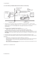
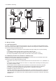
PH202S-B
or PH202S-D
Transmitter
-
+
Transmitter
-
+
Unclassified Location
Classified Location
Division 2
FM Approved
Power Supply
Voc d 32 VDC
Sensor
Connections
Max. cablelength: 60 mtr.
Cable dia.: 3…12 mm.
FM Class I, DIV. 2, Group ABCD
T4 for ambient temp. d 55 qC
T6 for ambient tem
p
. d 40 qC
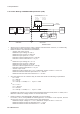
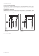
Sensor
Connections
-
+
-
+
FM Approved
Terminator
R = 90..100
C = 0..2,2 F
FM Approved
Terminator
R = 90..100
C = 0..2,2 F
x Sensor(s) are of a passive type to be regarded as 'simple apparatus', devices which
neither store nor generate voltages over 1.5 V, currents over 0.1 A, power over 25 mW or
energy over 20 PJ, or are FM Approvals entity approved and meet connection
requirements.
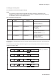
x Electrical data of the PH202S-B & PH202S-D:
- Supply circuit: Vmax=32 V; Pi=5.32 W; Ci= 220 pF; Li= 0 H
- Sensor input circuit: Vt=14.4 V; It=32.3 mA; Ca = 2.29 F; La = 64.96 mH
When installing this equipment, follow the manufacturers installation drawing.
Installation shall be in accordance with Article 501.4(B) of the National Electrical
Code (ANSI/NFPA 79).
Non-incendive field wiring may be installed in accordance with Article 501.4(B)(3)
x Grounding shall be in accordance with Article 250 of the National Electrical code.
x In case of using cable glands in Outdoor location, they shall be UV rated or made of metal.
WARNING
- Substitution of components may impair suitability for Division 2.
- Do not remove or replace while circuit is live unless area is know to be non-hazardous
- Explosion Hazard – Do not disconnect equipment unless area is know to be
non-hazardous
- Do not reset circuit breaker unless power has been removed from the equipment or the
area is know to be non-hazardous
2-14. Control Drawing of PH202S FF/PB Specification (FM Non-incendive FNICO)
Application Doc. No.: IKE025-A10 P.9