
User guide
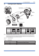

<5. Installing Impulse Piping>
5-1
IM 01C25F01-01E
5. Installing Impulse Piping
5.1 Impulse Piping Installation
Precautions
The impulse piping that connects the process
outputs to the transmitter must convey the process
pressure accurately. If, for example, gas collects in
a liquidlled impulse line, or the drain for a gas-lled
impulse line becomes plugged, it will not convey the
pressure accurately. Since this will cause errors in
the measurement output, select the proper piping
method for the process uid (gas, liquid, or steam).
Pay careful attention to the following points when
routing the impulse piping and connecting the
impulse piping to a transmitter.
5.1.1 Connecting Impulse Piping to a
Transmitter
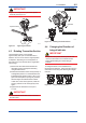
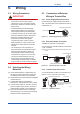
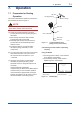
IMPORTANT
The transmitter can be installed in horizontal
impulse piping conguration, tilting the
transmitter's position up to 90°. When tilting,
observe that the pipe (for Model EJ530 and
EJX630A with measurement span code A, B,
and C) is positioned horizontal downwards, or
any place between them, as shown in Figure 5.1
The zero-adjustment screw must be positioned
downwards for all the models.
F0501.ai
If the zero-adjustment screw is positioned other than
donwards after installation, rotate the housing unitl it is
positioned downwards.
The pipe (open to atmosphere) is positioned horizontal.
Zero-adjustment screw
Pipe
(backside of the instrument)
Figure 5.1 Horizontal Impulse Piping Connection
5.1.2 Routing the Impulse Piping
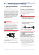
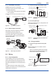
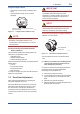
(1) Process Pressure Tap Angles
If condensate, gas, sediment or other extraneous
material in the process piping gets into the impulse
piping, pressure measurement errors may result. To
prevent such problems, the process pressure taps
must be angled as shown in gure 5.2 according to
the kind of uid being measured.
NOTE
• If the process uid is a gas, the taps must be
vertical or within 45° either side of vertical.
• If the process uid is a liquid, the taps must
be horizontal or below horizontal, but not
more than 45° below horizontal.
• If the process uid is steam or other
condensing vapor, the taps must be
horizontal or above horizontal, but not more
than 45° above horizontal.
[Gas]
Pressure
taps
Process
piping
[Steam][Liquid]
45°
45°
45° 45°
45°
45°
F0502.ai
Figure 5.2 Process Pressure Tap Angle
(For Horizontal Piping)
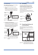
(2) Position of Process Pressure Taps and
Transmitter
If condensate (or gas) accumulates in the impulse
piping, it should be removed periodically by
opening the drain (or vent) plugs. However, this will
generate a transient disturbance in the pressure
measurement, and therefore it is necessary to
position the taps and route the impulse piping so
that any extraneous liquid or gas generated in the
leadlines returns naturally to the process piping.
• If the process uid is a gas, then as a rule the
transmitter must be located higher than the
process pressure taps.
• If the process uid is a liquid or steam, then as a
rule the transmitter must be located lower than
the process pressure taps.