User’s Manual DPharp BRAIN Communication Type (EJXA, EJAE) IM 01C25T03-01E IM 01C25T03-01E 5th Edition
i DPharp BRAIN Communication Type IM 01C25T03-01E 5th Edition Contents 1. Introduction................................................................................................ 1-1 Regarding This Manual................................................................................................. 1-1 2. 3. 1.1 Safe Use of This Product ................................................................................. 1-1 1.2 Warranty..........................................................
ii (10) CPU Failure Burnout Direction and Hardware Write Protect .. 3-11 (11) Software Write Protect ............................................................ 3-12 (12) Output Status Setup when a Hardware Error Occurs . ........... 3-13 (13) Bi-directional Flow Measurement Setup.................................. 3-13 (14) Range Change while Applying Actual Inputs .......................... 3-13 (15) Sensor Trim..............................................................................
1. 1-1 <1. Introduction> Introduction Thank you for purchasing the DPharp EJX series pressure transmitter/EJA series pressure transmitter (“transmitter”). The transmitters are precisely calibrated at the factory before shipment. To ensure both safety and efficiency, please read this manual carefully before operating the instrument.
(a) Installation • This instrument may only be installed by an engineer or technician who has an expert knowledge of this device. Operators are not allowed to carry out installation unless they meet this condition. • With high process temperatures, care must be taken not to burn yourself by touching the instrument or its casing. • Never loosen the process connector nuts when the instrument is installed in a process. This can lead to a sudden, explosive release of process fluids.
1.3 <1. Introduction> 1-3 ATEX Documentation This section is only applicable to the countries in the European Union.
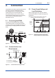
2. 2-1 <2. Connection> Connection The BRAIN communication signal is superimposed onto the 4 to 20 mA DC analog signal. Since the modulated wave is a communication signal, superimposing it on the normal signal will, from basic principles, cause no error in the DC component of the analog signal. Thus, monitoring can be performed via the BT200 while the transmitter is on-line. 2.1 2.
2.4 <2. Connection> 2-2 Integral Indicator Display When Powering On For models with the integral indicator code “D”, the display shows all segments in the LCD and then changes to the displays shown below sequentially. All segments display Model name (3 s) Communication Protocol (3 s) – – – – (3 s) F0200.ai NOTE For output signal code “D”, this function is available for software revision 2.02 or later. Software revision can be checked by the parameter M15: SOFT REV.
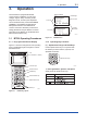
3. 3-1 <3. Operation> Operation The transmitter is equipped with BRAIN communications capabilities, so that range changes, Tag No. setup, monitoring of selfdiagnostic results, and zero point adjustment can be handled remotely via the BT200 BRAIN TERMINAL, the FieldMate Versatile Device Management Wizard or the CENTUM CS console. This section describes procedures for setting parameters using the BT200. For further information on the BT200, see the BT200 User’s Manual (IM 01C00A11-01E).
3-2 <3. Operation> b. Entering Alphabetic Characters (2) Function Keys Press either the left or right shift key and then an alphanumeric key to enter the desired alphabetic character. The shift key must be pressed each time an alphabetic character is entered. The function command carried out by each function key is displayed directly above the key. Letter on left side of the alphanumeric key Letter on right side of the alphanumeric key Entry F0308.ai Function Command List J. B F0305.
3-3 <3. Operation> 3.1.3 Calling Up Menu Addresses Using the Operating Keys UTILITY SCREEN --WELCOME-BRAIN TERMINAL ID: BT200 STARTUP SCREEN check connection push ENTER key UTIL The utility screen contains the following items. 1. BT200 ID settings 2. Security code settings 3. Switching language of messages (Japanese or English) 4. LCD contrast setting 5. Adjusting printout tone (BT200-P00 only) UTILITY 1.ID 2.SECURITY CODE 3.LANGUAGE SELECT 4.LCD CONTRAST 5.
3.2 Setting Parameters Using the BT200 3.2.1 Parameter Usage and Selection Before setting a parameter, please see the following table for a summary of how and when each parameter is used. Table 3.1 3-4 <3. Operation> IMPORTANT After setting and sending data with the BT200, wait 30 seconds before turning off the transmitter. If it is turned off too soon, the settings will not be stored in the transmitter. Parameter Usage and Selection Setup item Tag No. setup Calibration range setup ►P.3-6 ►P.
3-5 <3. Operation> 3.2.2 Menu Tree HOME A: DISPLAY B: SENSOR TYPE A10: OUTPUT A11: PRES A15: OUTPUT mA A16: ENGR. OUTPUT A17: ENGR. EXP A20: SP %*1 A21: SP*1 A30: CAPSULE TEMP A60: SELF CHECK B10: MODEL B11: STYLE NO. B20: PRES LRL B21: PRES URL B22: P MIN SPAN B30: SP LRL*1 B31: SP URL*1 B32: SP MIN SPAN*1 B60: SELF CHECK SET C: BASIC SETUP D: AUX SET 1 E: AUX SET2 G: ALARM SET H: AUTO SET I: DISP SET C10: TAG NO.
3-6 <3. Operation> 3.2.3 Setting Parameters Set or change the parameters as necessary. After completing these, do not fail to use the “DIAG” key to confirm that “GOOD” is displayed for the selfdiagnostic result at _60: SELF CHECK. (1) Tag No. Setup (C10: TAG NO) This is the panel for confirming set data. The set data items flash. When all items have been confirmed, press the again. (To go back to the setting panel, press the (NO) key. SET C10:TAG NO.
b. Setting Calibration Range Lower Range Value and Upper Range Value (C21: PRES LRV, C22: PRES URV) • Example 2: With present settings of 0 to 30 kPa, set the upper range value to 10 kPa. These range values are set as specified in the order before the instrument is shipped. Follow the procedure below to change the range. • The measurement span is determined by the upper and lower range limit values.
(4) Output Mode and Integral Indicator Display Mode Setup (C40: OUTPUT MODE, I20: P DISP MODE) (5) Output Signal Low Cut Mode Setup (D10: LOW CUT, D11: LOW CUT MODE) The mode setting for the output signal and the integral indicator can be performed independently. This mode is set as specified in the order when the instrument is shipped. Follow the procedure below to change the mode.
The low cut point has hysteresis so that the output around the point is behaved as below figure. Output mode: Linear Low cut mode: Zero Low cut: 20.00% Output Low cut point Setting range: 0 to 20% (6) Integral Indicator Scale Setup The following five displays are available for integral indicators: input pressure*1, % of range, user set scale, input static pressure, and % of static pressure range*1.
a. Display Selection (I10: DISP OUT1) • Example: Set an engineering unit M. Select the variable for the parameter I10: DISP OUT1 to display on the integral indicator. Set M. SET I30:ENGR.UNIT Press the M_ • Example: Change the integral indicator scale from % of range to input pressure display. Use the SET I10:DISP OUT1 PRES % < PRES < PRES % < ENGR.PRES < SP > > > > ESC SET I10:DISP OUT1 PRES FEED 3-10 <3. Operation> key to select PRES.
3-11 <3. Operation> d. Setting Static Pressure Unit and Scale (D30: SP UNIT, D33: SP LRV, and D34: SP URV) (9) Impulse Line Connection Orientation Setup (D15: H/L SWAP) Static pressure can be displayed in measured input static pressure or in %, independent from the 4-20 mA output signal of measured pressure or differential pressure. These parameters allow the entry of the static pressure unit and scale to be displayed. This function reverses the impulse line orientation.
Standard specifications a. Setting Password (D57: NEW PASSWORD) The burnout direction switch is set to HIGH. If a failure occurs, the transmitter outputs a 110% or higher signal. • Example: Set the password to 1234ABCD. Enter 1234ABCD. SET D57:NEW PASSWORD Press the to enter the setting. 1234ABCD Option code /C1 The burnout direction switch is set to LOW. If a failure occurs, a –5% or lower output is generated. CODE CAPS CLR FEED Slide switch position: H Press the (OK) key.
(12) Output Status Setup when a Hardware Error Occurs (D26: ERROR OUT) ● Output mode “LINEAR” 20 mA (100% display) This parameter allows the setting of the output status when a hardware error occurs. The following selections are available. (a) BURNOUT DIR; Outputs the corresponding values of 110% or –5% of output signals according to the setting by burnout direction switch (BO) on the CPU board. (b) HOLD; Outputs the last value held before the error occurred.
Note that changing the upper range value does not cause the lower range value to change but does change the span. • Example 2: When the upper range value is to be changed to 10 kPa with the present setting of 0 to 30 kPa, take the following action with an input pressure of 10 kPa applied. SET H11:AUTO P URV 30 kPa + 30 Press the key twice. The upper range value is changed to 10 kPa. ESC Press the SET H11:AUTO URV 10.000 kPa FEED 3-14 <3.
3-15 <3. Operation> a-3. Using External Zero-adjustment Screw Transmitter measures pressure of 0.03585 kPa. A11:PRES 0.03585 kPa SET J11:P ZERO ADJ 0.00000 kPa + 0 DEL CLR A pressure of 0 kPa is applied. Press the ESC SET J11:P ZERO ADJ 0.00000 kPa FEED NO key twice after the pressure has become stable. Note that the parameter J55: EXT ZERO ADJ must be ENABLE to perform this adjustment. Zero adjustment is completed.
b-1. Auto Sensor Trim b-2. Manual Sensor Trim • Example: For the range of 10 to 30 kPa. Setting a lower point Transmitter indicates 9.94 kPa as SET J10:ADJ PRES 9.94000 kPa its output when applying a standard pressure of 10 kPa. ESC SET J11:P ZERO ADJ 9.94000 kPa + 10 DEL CLR Set 10. • Example: For the range of 10 to 30 kPa. J15: P ZERO DEV = –0.04 kPa J16: P SPAN DEV = –0.03 kPa Suppose that a standard pressure of 10 kPa is applied and the value of the parameter J10: ADJ PRES is 9.94 kPa.
<3. Operation> c. Sensor Trim for Static Pressure (J21: SP ZERO ADJ, J22: SP SPAN ADJ, J25: SP ZERO DEV, J26: SP SPAN DEV) NOTE For the transmitters (Except for EJX120A/EJA120E), zeroing and full sensor trim of the static pressure is performed in the same way as with the primary process variable (PV). Note that the static pressure sensor trim should be done only after trimming the PV. d.
• Example: Set the number of coodinates on the line graph to 5. Set 5. SET T11:NUM OF POINT 9 5 CLR Press the NO key twice to enter the setting. ESC Press the SET T11:NUM OF POINT 5 FEED 3-18 <3. Operation> (OK) key. • Example: Set alarm mode from OFF to HI.AL DETECT. SET G10:P AL MODE INHIBIT < INHIBIT < HI.AL DETECT < LO.AL DETECT < HI/LO.AL DETECT Use the > > > > ESC SET G10:P AL MODE HI.AL DETECT OK FEED NO or key to select HI. AL DETECT.
• Example: Set the status output to output an off signal when the input pressure exceeds 75 kPa with its alert mode of HI. AL DETECT. Use the SET E50:DO SELECT INHIBIT < INHIBIT < PRES < SP < TEMP > > > > ESC SET E50:DO SELECT PRES FEED or key to select PRES. Press the key twice to enter the setting. Press the (OK) key. OK Use the SET E51:DO SIG.TYPE ON WHEN ALARM < ON WHEN ALARM < OFF WHEN ALARM > > ESC SET E51:DO SIG.TYPE OFF WHEN ALARM NO or key to select OFF WHEN ALARM.
3-20 <3. Operation> (21) Adjustment Information and User Memo Fields (J50: ADJ WHO, J51: ADJ DATE, J52: ADJ LOC, J53: ADJ DESC, M17 to M19: MEMO1 to MEMO3) ● EJX118A/EJA118E L h (+) 0 Transmitter H This feature provides four fields for instrument adjustment information at maintenance: inspection date, inspector, location, and description. Also three user memo fields are provided, each holding up to 16 alphanumeric characters.
<3. Operation> 3-21 3.3.2 Display Transmitter Model and Specifications The BT200 can be used to display the model and specifications of the transmitter. • Example: View transmitter model name. MENU A:DISPLAY B:SENSOR TYPE C:BASIC SETUP D:AUX SET1 E:AUX SET2 G:ALARM SET HOME SET ADJ PARAM B10:MODEL EJX110 M B11:STYLE NO. 1.00 B20:PRES LRL - 98.07 kPa DATA DIAG PRNT Press . ESC For the associated parameters, see Chapter 5, Parameter Summary. ESC F0357.
4. 4-1 <4. Self-diagnostics> Self-diagnostics 4.1 Checking for Problems • Example 3: Checking the history of the errors 4.1.1 Identifying Problems with BT200 The following four areas can be checked. (a) Whether connections are good. (b) Whether BT200 was properly operated. (c) Whether settings were properly entered. (d) History of the errors. See examples below. • Example 1: Connection errors Press the --WELCOME-BRAIN TERMINAL ID: BT200 check connection push ENTER key UTIL key.
4-2 <4. Self-diagnostics> 4.1.2 Checking with Integral Indicator NOTE If an error is detected by running self-diagnostics, an error number is displayed on the integral indicator. If there is more than one error, the error number changes at three-second intervals. See table 4.1 regarding the alarm codes. 4.2 F0404.ai Figure 4.1 Integral Indicator Alarms and Countermeasures Table 4.1 Indicator Alarm Message Summary BT200 display None GOOD AL. 01 01: P-SENSOR ERR CAP. ERR Cause Sensor problem.
<4. Self-diagnostics> Indicator AL. 50 P. LRV AL. 51 P. URV AL. 52 P. SPN AL. 53 P. ADJ AL. 54 SP. RNG AL. 55 SP. ADJ AL. 60 SC. CFG AL. 79 OV. DISP BT200 display 50: P ILLEG LRV Cause Specified value is outside of setting range. 51: P ILLEG URV Output operation during error Holds output immediately before error occurred. 4-3 Countermeasure Check settings and change them as needed.
5. 5-1 <5. Parameter Summary> Parameter Summary Item *1 R/W No. Parameter name 01 MODEL Model R 02 03 A A10 A11 TAG No. SELF CHECK DISPLAY OUTPUT PRES R R A15 A16 A17 A20 A21 OUTPUT mA ENGR. OUTPUT ENGR.
No. Parameter name D D10 D11 D15 AUX SET 1 LOW CUT LOW CUT MODE H/L SWAP D16 H2O UNIT SEL D20 D21 D22 D25 D26 D30 D31 OUT LIMIT (L) OUT LIMIT (H) REV OUTPUT BURNOUT ERROR OUT SP UNIT SP A/G SLCT D32 ATM. PRESS D33 5-2 <5. Parameter Summary> Item Auxiliary setting data 1 Low cut Low cut mode Impulse piping accessing direction H2O unit select *1 R/W Content Default value Applicable model F P L Upload data W W W 0.00 to 20.00% LINEAR or ZERO NORMAL or REVERSE 10.
No. Parameter name Item *1 R/W G ALARM SET G10 P AL MODE Alarm setting Alert mode W G11 High side alert value W G12 P LO. AL VAL Low side alert value W G20 SP AL MODE Static pressure alert mode W G21 SP HI. AL VAL High side alert value of SP*2 W G22 SP LO. AL VAL Low side alert value of SP W G30 T AL MODE Temperature alert mode W G31 T HI. AL VAL P HI. AL VAL 5-3 <5. Parameter Summary> Content Default value Applicable model F P L Upload data INHIBIT — 100.
Item *1 R/W ADJUST ADJ UNIT ADJ PRES P ZERO ADJ Adjusting data Pressure adjusting unit select Adjustment reference pressure Automatic zero adjustment W R W J12 P SPAN ADJ Automatic span adjustment W J15 P ZERO DEV Manual zero adjustment W J16 P SPAN DEV Manual span adjustment W J20 ADJ SP R J21 SP ZERO ADJ Adjustment reference pressure of SP Automatic SP zero adjustment J22 SP SPAN ADJ J25 No. Parameter name J J09 J10 J11 5-4 <5. Parameter Summary> Content Default value 0.
5-5 <5. Parameter Summary> Item *1 R/W Content Default value Applicable model F P L Upload data No.
A1-1 Appendix 1. Safety Instrumented Systems Installation WARNING The contents of this appendix are cited from exida.com safety manual on the transmitters specifically observed for the safety transmitter purpose. When using the transmitter for Safety Instrumented Systems (SIS) application, the instructions and procedures in this section must be strictly followed in order to preserve the transmitter for that safety level. A1.
Table A1.2 A1-2 Proof Testing Testing method Functional test: 1. Follow all Management of Change procedures to bypass logic solvers if necessary. 2. Execute HART/BRAIN command to send value to high alarm (21.5 mA) and verify that current has reached this level. 3. Execute HART/BRAIN command to send value to low alarm (3.6 mA) and verify that current has reached this level. 4. Restore logic solvers operation and verify.
A1.3 Definitions and Abbreviations A1.3.2 Abbreviations FMEDA Failure Mode, Effects and Diagnostic Analysis A1.3.
i Revision Information Title : DPharp BRAIN Communication Type Manual No. : IM 01C25T03-01E Edition 1st 2nd 3rd Date Apr. 2004 Oct. 2004 Aug. 2009 4th Jun. 2012 5th Jun. 2013 Page — 3-19 3-8 3-14 3-18 2-2 3-5 3-6 3-12 3-15 3-17 3-20 5-1 5-3 5-4 Revised Item New publication. 3.2.3(20) • Add capillary fill fluid density compensation setting procedure. 3.2.3(5) • Add example for hysteresis. 3.2.3(15) • Correct misprint. 3.2.3(19) • Add CAUTION. Add note for hysteresis. 2.