
Owner's manual


<9. General Specications>
9-20
IM 01C25B01-01E
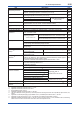
Item Description Code
Oil-prohibited use with
dehydrating treatment *
4
Degrease cleansing treatment and dehydrating treatment.
K5
Degrease cleansing treatment and dehydrating treatment with uorinated oillled
capsule. Operating temperature –20 to 80°C( –4 to 176°F)
K6
Capsule ll uid Fluorinated oil lled in capsule
Operating temperature –20 to 80°C( –4 to 176°F)
K3
Calibration units *
5
P calibration (psi unit)
(See Table for Span and
Range Limits.)
D1
bar calibration (bar unit) D3
M calibration (kgf/cm
2
unit) D4
Long vent *
6
Total length: 119 mm (standard: 34 mm); Total length when combining with
Optional code K1, K2, K5, and K6: 130 mm. Material: 316SST.
U1
Gold-plated capsule gasket
*
13
Gold-plated 316L SST capsule gasket. No PTFE is used for wetted parts.
GS
Gold-plated diaphragm *
14
Surface of isolating diaphragm is gold plated, effective for hydrogen permeation. A1
130 Pa abs calibration *
12
Minimum input puressure at calibration testing: 130 Pa abs (1 mmHg abs) S1
Output limits and failure
operation *
7
Failure alarm down-scale: Output status at CPU failure and hardware error is
–5%, 3.2 mA DC or less.
C1
NAMUR NE43 Compliant
Output signal limits:
3.8 mA to 20.5 mA
Failure alarm down-scale: Output status at CPU
failure and hardware error is –5%, 3.2 mA DC or less.
C2
Failure alarm up-scale: Output status at CPU
failure and hardware error is 110%, 21.6 mA or more.
C3
Body option *
8
Without drain and vent plugs N1
N1 and Process connection, based on IEC61518 with female thread on both sides
of cover ange, with blind kidney anges on back.
N2
N2 and Material certicate for cover ange, diaphragm, capsule body, and blind
kidney ange
N3
Stainless steel tag plate 304SST tag plate wired onto transmitter N4
Data conguration at
factory *
9
Data conguration for HART
communication type
Software damping, Descriptor, Message
CA
Data conguration for BRAIN
communication type
Software damping
CB
European Pressure
Directive *
10
PED 97/23/EC
Category: III, Module: H, Type of Equipment; Pressure Accessory-Vessel, Type of
Fluid; Liquid and gas, Group of Fluid: 1 and 2
Lower limit of Process and Ambient temperature for EJX110A : –29°C
PE3
Advanced diagnostics *
27
Multi-sensing process monitoring
• Impulse line blockage detection *
28
• Heat trace monitoring
DG6
Material certicate *
15
Cover ange *
16
M01
Cover ange, Process connector *
17
M11
Pressure test/
Leak test certicate
Test Pressure: 16 MPa (2300 psi) *
18
Nitrogen(N
2
) Gas *
25
Retention time: one minute
T12
Test Pressure: 25 MPa (3600 psi) *
19
T13
Test Pressure: 3.5 MPa (500 psi)*
20
T01
Test Pressure: 500 kPa (2000 inH
2
O) *
21
T11
Test Pressure: 50 kPa (200 inH
2
O) *
22
T04
Test Pressure: 32 MPa (4500 psi) *
23
Nitrogen(N
2
) Gas or water *
26
Retention time: one minute
T09
Test Pressure: 50 MPa (7200 psi) *
24
T08
High accuracy type High accuracy HAC
High pressure-proof
structure
Maximum working pressure for differential pressure measurement: 25MPa*
29
HG
Contact Yokogawa representative for the codes indicated as ‘-’.
*1: Applicable for Electrical connection code 2, 4, 7, and 9.
*2: Applicable for Electrical connection code 2 and 7.
*3: Not applicable for option code /AL.
*4: Applicable for Wetted parts material code S, H, M, and T.
*5: The unit of MWP (Max. working pressure) on the name plate of the housing is the same unit as specied by Option code D1, D3,
and D4.
*6: Applicable for vertical impulse piping type (Installation code 7) and Wetted parts material code S, H, M, and T.
*7: Applicable for output signal code D, E and J. The hardware error indicates faulty amplier or capsule.
*8: Applicable for Wetted parts material code S, H, M, and T; Process connection code 3, 4, and 5; Installation code 9; and Mounting
bracket code N. Process connection faces on the other side of zero adjustment screw.