
User guide

7-8
IM DR231-11E
7.7 System Configuration Output Format
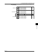
The measurement interval and system connection data are output in the following format by the
TS5 + “Device Trigger (GET)” + CF command:
M : sssssCrLf
S1 : 0=MMMMMM(DD)1=MMMMMM(DD)~5=MMMMMM(DD)CrLf
Slot number
Each symbol denotes the following:
M: Measurement interval mark
sssss: Measurement interval; output down to one decimal place (Example: 10.0
for a measurement interval of 10 sec.). The unit is “second.”
S1: Subunit number
I ------------------ Main unit (DR232/DR242)
0------------------ Subunit or DR130/DR231/DR241
1 to 5 ------------ Subunit
E ----------------- End mark
MMMMMM: Module name (6 characters)
COMM---------- Communication module
RELAY --------- Relay output module
REMOTE ------- Remote module
INPUT ---------- Universal input module
mA--------------- mA-input module
AC --------------- Power monitor module
STRAIN -------- Strain input module
PULS ------------ Puls input module
DI ---------------- Digital input module
ERROR --------- Module error
(DD): Internal code (hexadecimal, ASCII, 2 characters)
Note
• The number and data of subunits not connected in the system settings are not output.