
User guide


4-4
IM DR231-11E
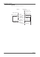
4.3 Names and Functions of Each Section
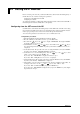
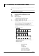
Tx (yellow)
)
LINK (yellow)
STS1 (green)
STS2 (green)
Status
Indicator LED
Dip Switch
1234
ON
OFF
10BASE-T Port
Connect the RJ-45 modular jack
of the twist pair cable connected
to the 10BASE-T network.
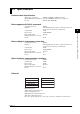
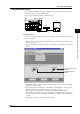
Setting the Dip Switch
You can select the following three modes by setting the dip switch.
Configuration mode: A mode in which the IP address, subnet mask, and default gateway are set
for theDR.
Test mode: A mode in which the condition of the physical connection is tested.
Communication mode: A mode in which the DR is connected to the network to carry out communi-
cation. Use this mode to read in the DR measurement data with the PC.
In addition, you can turn ON/OFF the Keepalive function.
Setting are effective only after the DR is reboot.
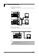
Mode Setting
Mode Switch 1 Switch 2
Configuration mode ON OFF
Test mode OFF ON
Communication mode OFF OFF ←Default setting
Do not set both dip switches, 1 and 2, to ON.
Keepalive Setting
Keepalive Switch 3
Enable ON ←Default setting
Disable OFF
Keepalive is a function supported by TCP. It sends packets at constant time intervals and automati-
cally disconnects when there is no corresponding response. This instrument sends packets at 30-
second time intervals. If a response is not received, it sends 4 more packets at one-second intervals.
If a response is still not received, the connection is dropped.
Have dip switch 4 turned OFF.
LED Indication
The LED indicates the communication conditions and errors of the DR.
Communication condition
LED(color) Indication Lit Not lit Blinking
Tx(yellow) Data transmission state Transmitting No transmission -
LINK(yellow) Connection state Connected Not connected -
(electronically, physically)
STS1(green) Communication mode: Established Not established Error
connection state
Configuration mode: Configuration updated Configuration not updated Error
configuration state
Test mode: test results No errors Testing Error