
Owner's manual

IM DR232-01E-9A 2/5
for IM DR232-01E 9th Edition
Page 2-18 “External In/Output Function (alarm module or DI/DO module is required)”
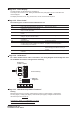
• Fail Output *
One transfer contact in the DI/DO module is used for fail output. This relay will change to the de-energized
status when a failure of the recorder occurs.
* Fails are output when CPU abnormalities, power failures, or other problems occur. They are not output as a result of
errors in recognizing I/O output modules or subunits, or of overranges or errors in measured data.
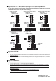
Page 3-5 “Installation Method”
• Direct panel mounting
Attach the unit to the 2 mm-thick metal plate using the 6 screws included (length : 16 mm) according to the
figure below.
Page 3-20 “WARNING”
············································································································
• When 30 VAC or 60 VDC and more is applied to the output terminal of the alarm output module or the output
terminal of the DI/DO module, use double-insulated wires (withstand voltage performance: more than 2300
VAC) for those wires which apply 30 VAC or 60 VDC and more. All other wires can be basic-insulated
(withstand voltage performance: more than 1390 VAC).··············································
• To prevent fire, use signal wires having a temperature rating of 75°C or more.
Page 3-20 “CAUTION”
············································································································
• The overvoltage category of each input module is CAT ll (IEC61010-1, CSA22.2 No.61010-1).
• The measurement category of each input module is CAT ll (IEC61010-1, CSA22.2 No.61010-1).
• When connecting to a clamp terminal, use a signal conductor with the following cross-sectional width:
············································································································