
Instruction Manual

3-16
IM DR231-01E
3.5 Connecting the Signal Lines
W WARNING
• To prevent electric shock always make sure that the power supply is
turned OFF before connecting.
• When 30VAC or 60VDC and more is applied to the output terminal of
the alarm module or the output terminal of the DI/DO module, use
double-insulated wires(withstand voltage performance: more than
2300VAC) for those wires which apply 30VAC or 60VDC and more. All
other wires can be basic-insulated(withstand voltage performance:
more than 1350VAC). Furthermore, use “crimp-on” lugs (for 4mm
screws) with insulation sleeves for connecting to the screw terminal.
Make sure that the crimp-on tool must be one specified by the crimp-on
lugs manufacture, and that the crimp-on lugs and tool must be matched
to the wire size. To prevent electric shock, do not touch the terminal
after wiring and make sure to re-apply the cover.
CAUTION
• Do not apply an input voltage exceeding the following levels to each
terminal of each module. Otherwise, the internal circuits may be
damaged.
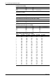
Allowable input voltage
Universal or DCV/TC/DI input module
2 VDC range or less, RTD, TC and DI(CONT) : ±10 VDC
6 to 20 VDC range, DI(LEVEL) : ±60 VDC
DI/DO module : –2 to 7 VDC
Max. common mode noise voltage
Universal or DCV/TC/DI input modules : 250 VACrms (50/60 Hz)
• Output contact rating for DI/DO or Alarm input modules is 250 VDC/0.1
A (resistive load), 250 VAC/2 A (resistive load), 30 VDC/2 A (resistive
load).
• The overvoltage categoly of each input module is CAT ll (IEC 1010).
• When connecting to a clamp terminal, use a signal conductor with the
following cross-sectional width:
Solid conductor 0.14 to 2.5 mm
2
Stranded conductor 0.14 to 1.5 mm
2
AWG 26 to 14
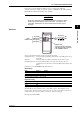
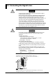
1 Check that the power switch of this instrument is turned off.
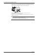
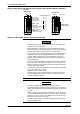
2 Remove the terminal cover. (the figure below shows DU100-11.)
Terminal cover
Screws for fastening the cover
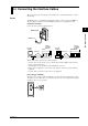
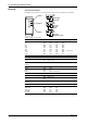
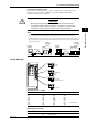
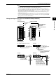
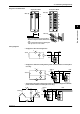
3 Fasten the signal wires to the terminals as shown in the figure on the next page.
4 Re-apply the terminal cover and fasten the screws.