
Instruction Manual

14-3
IM DR231-01E
Specifications
14
14.1 Specifications of DR130/DR231/DR241 (Style S3)
Measurement interval
DR130 : Selectable from 2, 3, 4, 5, 6, 10, 12, 15, 20, 30 or 60s; max. 2s/20ch (measured with
20ch, filter:OFF, A/D integration time: 20ms(50Hz)/16.7ms(60Hz))
DR231/DR241 : Selectable from 2, 3, 4, 5, 6, 10, 12, 15, 20, 30 or 60s; max. 2s/30ch (measured
with 30ch, filter:OFF, A/D integration time: 20ms(50Hz)/16.7ms(60Hz))
Noise rejection
Rejection by integration type A/D, lowpass filter, or moving averaging.
Input resistance
Min. 10MΩ at 2V DC or lower and thermocouple range
Approx. 1MΩ at 6V DC or higher.
Insulation resistance
Min. 20MΩ at 500V DC between the input terminal and ground.
Input bias current
max. 10nA
Dielectric strength
Between input terminals : 1000V AC (50/60Hz) for one minute
Between an input terminal and ground : 1500V AC (50/60Hz) for one minute
Input source resistance
DCV, TC : 2kΩ or lower
RTD : 10Ω or lower per line (Pt100Ω)
5Ω or lower per line (Pt50Ω)
1Ω or lower per line (Cu10Ω)
Temperature coefficient
zero : 0.01% of range/°C
full span : 0.01% of range/°C (0.02% of span/°C for CU10Ω)
Thermocouple burnout
Detected in a TC range (On/Off) enabled, current of 4µA, detectable pulse width of approx. 5ms
2 kΩ or lower is considered “normal”
100 kΩ or greater is considered “disconnected”
Detection interval for thermocouple burnout
Detected at each measurement interval.
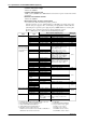
Input Type
Power monitor
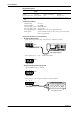
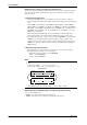
Terminal Configuration
Single-phase use (one channel each for voltage and current): clamp
Three-phase use (three channels each for voltage and current): clamp
Shortest Measurement Interval
2 s
Method of Input
Transformer-isolated input, with isolation between channels (separated channels)
Method of Measurement and Computing
Digital multiplication
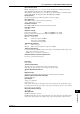
Input Ranges
Voltage: 25 or 250 Vrms
Current: 0.5 or 5 A
In three-phase measurement or single-phase three-wire measurement, the current/voltage ranges
are identical between the respective phases or lines (the current/voltage ranges are set in common
between the respective channels).
Measured Frequency Range
45 to 65 Hz
Wiring Methods
DU400-12: Single-phase two-wire
DU400-22: Single-phase two-wire, single-phase three-wire, three-phase three-wire (dual-voltage,
dual-current), three-phase three-wire (triple-voltage, triple-current) and three-phase four-wire