
Instruction Manual

13-4
IM DR231-01E
13.3 Troubleshooting
If an error code appears on the display, see Section 13.4, “Error Codes.”
If servicing is necessary, or if the instrument is not operating correctly though the following
corrective actions have been taken, please contact your nearest sales representative. Addresses
may be found on the back cover of this manual.
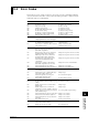
Problem Probable Cause Corrective Action
Recorder does not operate. Power switch is off. Turn on the power. There is also an AC power switch on the back
panel on the DC power supply model.
(The recorder carriage and chart do Power supply is not Connect properly.
not move.) connected properly.
Supplied power does not Use power meeting its requirements.
meet powerrequirements.
Fuse blown. Replace fuse. (If the fuse blows immediately after turning on the
power, servicing will be required.)
Output beyond its limits Input specifications are not Correct input specifications.
Fluctuating indication correct.
Carriage swung over.
Incorrect measuring range or Change measuring range or recording span.
recording span
Noise superimposed. Connect input wiring far away from noise source.
Ground recorder.
Ground measurement object.
Isolate thermocouple from measurement object.
Use shielded wiring for input line.
Change A/D integral times.
Use moving average.
Use input filter.
No countermeasure taken Install input terminal cover properly.
against ambient temperature
changes.
Protect recorder from blowing air of fan.
Keep temperature changes near input terminals small.
Input connected improperly. Connect input properly.
Connect module properly.
Tighten screws properly.
Isolate RTD from ground.
Replace disconnected thermocouples.
Recorder connected in parallel Do not use burnout functions in other instruments.
with other instruments.
Ground recorder and other instruments in the same ground line.
Do not connect recorder in parallel with other instruments
(for use with dual-element TC).
RJC set improperly Set RJC properly.
(for TC input)
Dot-printing position Calibrate correctly.
not calibrated correctly.
Other cause. Contact your nearest sales representative.
Defective display Noise superimposed. Lay input wiring far away from noise source.
Ground recorder.
Ground measurement object.
Isolate TC from measurement object.
Use shielded wires for input line.
Change A/D integration times.
Use input filter.
DC supply voltage is low. Increase the input voltage or use a thicker wire to lower the wire
resistance (The voltage at the DC power supply connector may be
lower than the operating supply voltage range due to the wire
resistance).
Data indicates “xxxxxx” Input module connected Connect input properly.
improperly
Recorder does not work even with Key-lock not released. Disable key-lock functions in setup mode.
operation key pressed.
Recorder set in remote mode. Set recorder in local mode.
Other cause. Contact your nearest sales representative.