
User Manual

IM 12J05D02-01E
3-10 Installation and wiring
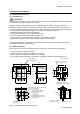
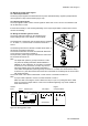
3-7. Wiring other galvanic sensors
Consult the users manual for the color identification of the sensor cable and connect temperature com-
pensator, cathode and anode to the terminals: 11, 12, 13 and 15 as described above.
Connect the cable shield to 14 if there is one available. Sensor diagnostics is normally not possible.
Note:
A jumper cable is placed to connect converter terminals 13 and 17.
Make sure that connecting the sensor cable to the IE pin or pin 13 or pulling the sensor cable
does not cause the jumper cable to come loose. Insufficient tightening may cause unstable or
false measurements.
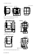
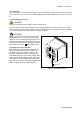
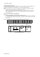
3-8. Wiring the standard optical sensor (DO70G)
Note:
A jumper cable is placed to connect converter terminals 13 and 17.
When a standard optical sensor (DO70G) is to be connected, the cable is not used, so disconnect
it. It is recommended to save the jumper cable for future use—if may be needed when a galvanic
sensor is used.
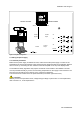
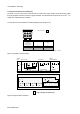
The color of the wiring of the sensor cable supports the indication of each terminal.
Color of sensor cable White Green Green/Yellow Clear Red Brown Blue
DO402G 11 12 14 17 18
DOX10 + –
F0311.ai
Digital
Communications
1213
1516
63 66 65 62 61 95 94 93 92 91
SCREEN
mA2
mA1
SCREEN
TL TL
17 11
CONT mA OUTPUT
14
22
21
18
SCREEN
99
SCREEN 2
23
Sensor Input
Temp.
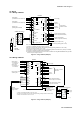
Wiring optical sensor
mA Output
Contact
Input
Shield
Figure 3-12. Wiring optical sensor