
User Manual

IM 12J05D02-01E
Installation and wiring 3-3
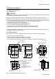
3-2. Wiring
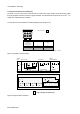
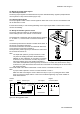
3-2-1. Wiring of DO30G
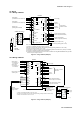
DO402G
61
62
65
66
63
21
22
23
13 IE
11 T1
12 T2
14
15 RE
16
mA 1
mA 2
Power supply
Contact
output S1
Contact
output S2
Contact output S3 (cleaning,
HOLD or high and low alarms)
Contact output S4/FAIL
(failure or high and low alarms)
Grounding terminal (M4 screw)
S1
N
L
S2
S3
S4
High and low
alarms or HOLD
DO30G
DO sensor
WTB10 Terminal box
Output signal
(4 to 20mA DC or 0 to 20mA DC)
Output signal
(4 to 20mA DC or 0 to 20mA DC)
Contact input
(cleaning start command)
Note : External wiring connection terminal size is for Ø2 pin.
Protective grounding (100Ω or less)
1
2
3
31
32
33
41
42
43
51
52
53
71
72
73
C
NC
NO
C
NC
NO
C
NC
NO
C
NC
NO
G
SCREEN
SCREEN
17
Jumper
Shield
Liquid earth *6
*1: Always use a shielded cable with an OD of 6 to 12 mm.
*2: Be sure to ground the DO converter case grounding terminal (grounding resistance of 100Ω or less).
*3: Always use a cable with an OD of 6 to 12 mm.
*4: Terminal box is used only where DO converter is installed long distance from DO sensor. (ordinary not needed)
*5: This cable is specified in the Basic Code for the WTB10.
*6: Liquid earth to detect membrane failure. This function is available when using PB350G/PB360G float type holder.
Connect only when using this function.
13
11
12
14
15
16
*4
*1
*1
*3
*3
*3
*2
*5
Figure 3-4. wiring of DO30G (Example)
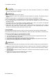
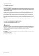
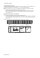
3-2-2. Wiring of DO70G
DO402G
61 +
62 −
65 +
66 −
63
21
22
23
mA1
mA2
Power supply
Contact
signal S1
Contact
signal S2
Contact signal S3(Cleaning,
HOLD or High and Low alarms)
Grounding terminal
(M4 screw)
Protective grounding
(100Ω or less)
S1
N
L
S2
S3
S4
High and Low alarms
and HOLD
Output signasl
(4 to 20mA DC or
0 to 20mA DC)
Output signal
(4 to 20mA DC or
0 to 20mA DC)
Remote contact input
(Cleaning start)
Note : External wiring connection terminal size is for Ø2 pin.
F11.eps
G
1
2
3
31
32
33
41
42
43
51
52
53
71
72
73
Contact signal S4/FAIL(Failure
or High and Low alarms)
C
NC
NO
C
NC
NO
C
NC
NO
C
NC
NO
L
N
G
L
N
G
11
12
14
17
18
DO70G
Optical dissolved
oxygen sensor
*1: Always use a shielded cable with an OD of 6 to 12 mm.
*2: Be sure to ground the DO converter case grounding terminal (grounding resistance of 100Ω or less).
*3: Always use a cable with an OD of 6 to 12 mm.
*1
*1
*3
*3
*2
White
Green
Green/Yellow
Clear
Red
*3
DOX10 Poewr supply unit
*3
*3
Power
supply
Brown
Blue
+ (BROWN)
‒ (BLUE)
Figure 3-5. wiring of DO70G (Example)