User’s Manual Model DO402G [Style: S3] Dissolved Oxygen Converter IM 12J05D02-01E IM 12J05D02-01E 8th Edition
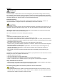
PREFACE WARNING Electric discharge The EXA analyzer contains devices that can be damaged by electrostatic discharge. When servicing this equipment, please observe proper procedures to prevent such damage. Replacement components should be shipped in conductive packaging. Repair work should be done at grounded workstations using grounded soldering irons and wrist straps to avoid electrostatic discharge.
WARNING This symbol indicates that the operator must refer to the instructions in this manual in order to prevent the instrument (hardware) or software from being damaged, or a system failure from occurring. CAUTION This symbol gives information essential for understanding the operations and functions. This symbol indicates Protective Ground Terminal This symbol indicates Function Ground Terminal (Do not use this terminal as the protective ground terminal.) This symbol indicates Alternating current.
TABLE OF CONTENTS PREFACE.....................................................................................................................1 1. Introduction And General Description.............................................................. 1-1 1-1. Instrument Check............................................................................................. 1-1 1-2. Application....................................................................................................... 1-2 1-3.
5-1-2. Manual Wash start/stop....................................................................................................5-3 5-1-3. Setpoint adjustment..........................................................................................................5-4 5-2. Commissioning mode...................................................................................... 5-5 5-2-1. 5-2-2. 5-2-3. 5-2-4. 5-2-5. Setpoints...................................................................................
11. Appendix 2 QUALITY INSPECTION.................................................................11-1 Customer Maintenance Parts List (for Style: S3) ..................CMPL 12J05D02-03E Revision Record ..........................................................................................................
Introduction 1-1 1. Introduction And General Description The Yokogawa EXA is a 4-wire coverter designed for industrial process monitoring, measurement and control applications. This instruction manual contains the information needed to install, set up, operate and maintain the unit correctly. This manual also includes a basic troubleshooting guide to answer typical user questions. Yokogawa can not be responsible for the performance of the EXA analyzer if these instructions are not followed. 1-1.
1-2 Introduction 1-2. Application The EXA converter is intended to be used for continuous on-line measurement in industrial installations. The unit combines simple operation and microprocessor-based performance with advanced self-diagnostics and enhanced communications capability to meet the most advanced requirements. The measurement can be used as part of an automated process control system.
Introduction 1-3 1-3. General information Flexibility, reliability and low maintenance are among the benefits provided by the EXA DO402G dissolved oxygen analyzer. Designed to meet the exacting requirements of measuring dissolved oxygen in the modern industrial environment, it contains many features to ensure the best precision whatever the application. This 4-wire converter is housed in a robust IP65 field mountable case.
1-4 Introduction Display functions and ranges The display continuously gives you all necessary information at a glance. The process values are shown in easily readable programmable units. Either mg/l. % saturation or ppm can be chosen. The user-interface is simplified to a basic set of 6 keys accessible through the flexible window cover.
Introduction 1-5 Logbook Software record of important events and diagnostic data. Available through RS485, for use with the Yokogawa PC402 communication software. Serial Communication Bi-directional according to the EIA-485 standard using HART-protocol and PC402 software. 1-4.
1-6 Introduction 1-5. System Configuration Holders, Holders with Cleaning System Dissolved Oxygen Sensor DO70G Guide Pipe PH8HG Floating Ball Holder PB350G PB360G Dissolved Oxygen Converter Output Signal: 4 to 20 m A DC or 0 to 20 m A DC DO402G Alarm Contact Output 4-Contact Point,High/Low Alarm Cleaning Time,Alarm Contact HOLD Contat DO30G 100V AC±15% 115V AC±15% 230V AC±15% (For DO30G) Terminal Box WTB10-DO3 Select pin terminal for DO402G.
Introduction 1-7 e. Ingold model 32 sensors with 12, 19 and 25 mm shaft These sensors are available in many different configurations. The sensor is a polarographic sensor and therefore settings of service code 01 has to be changed from 0 to 1. The sensor output is normally between 30 and 100 nA in ambient air under reference conditions, but the “large cathode” version has a current output between 200 and 700 nA.
Specification 2-1 2. DO402G SPECIFICATIONS 2-1. General A. Input specifications : The DO402G Dissolved Oxygen converter measures the current, that is generated by the Dissolved Oxygen sensor. The flexibility of the input circuit allows the use of many commercially available sensors, whether they are of the Galvanic type (driving voltage generated internally) or Polarographic type (driving voltage supplied by converter) The input range varies from 0.
2-2 Specification J. Contact outputs - General : Four (4) SPDT relay contacts with LED indicators. For S1, S2, and S3, the LED is on when relay is powered. NOTE: For S4 (FAIL) LED lights when power is removed (Fail safe). C ontact outputs configurable for hysteresis and delay time. - Capacity : Maximum values 100 VA, 250 V AC, 5 Amps. Maximum values 50 Watts, 250 V DC, 5 Amps. - Status : High/Low process alarms, selected from process parameters and temperature.
Specification 2-3 B. Performance : Temperature (Pt1000, PB36, 22kNTC) - Linearity : ± 0.3 ºC - Repeatability : ± 0.1 ºC - Accuracy : ± 0.3 ºC Performance : Temperature (Pt100) - Linearity : ± 0.4 ºC - Repeatability : ± 0.1 ºC - Accuracy : ± 0.4 ºC Note on performance specifications: The specifications are expressed with simulated inputs, because the DO402G can be used with many different sensors with their unique characteristics. The following tolerance is added to above performance.
Installation and wiring 3-1 3. Installation And Wiring 3-1. Installation and dimensions 3-1-1. Installation site WARNING This instrument is a Class A product, and it is designed for use in the industrial environment. Please use this instrument in the industrial environment only. The EXA converter is weatherproof and can be installed inside or outside. It should, however, be installed as close as possible to the sensor to avoid long cable runs between sensor and converter.
3-2 Installation and wiring 23 (0.91) 12 max.(panel thickness) Unit: mm (inch) M6, 4 screws Panel cutout dimensions (0.47) M5, 2 screws 137 +20 100 (3.94) (5.43) 137 +20 (5.43) 178 (7.01) Figure 3-2 . Panel mounting diagram (Option Code: /PM) Example of bracket used for pipe mounting 188 M6, 4 screws (7.40) 174 (6.85) 200 (7.87) 50 (1.97) Nominal 50A (O.D 60.5mm) (2 inch) mounting pipe 100 (3.94) Example of bracket used for wall mounting 135 (5.31) 13 M6, 4 screws (0.
Installation and wiring 3-3 3-2. Wiring 3-2-1.
3-4 Installation and wiring DANGER • Never apply power to the DO402G converter and other instruments connected to the DO402G converter until all wiring is completed. WARNING • This product complies with the CE marking. Where compliance with the CE marking and relevant standard is necessary, the following wiring is required. 1.Install an external switch or circuit breaker to the power supply of the DO402G converter. 2.
Installation and wiring 3-5 front glands rear glands Sensor output signals Power contact output S1 S2 rs485 contact output S3 S4/FAIL contact intput Figure 3-6. System configuration 3-3. Wiring the power supply 3-3-1. General precautions Make sure the power supply is switched off. Also, make sure that the power supply is correct for the specifications of the EXA and that the supply agrees with the voltage specified on the textplate.
3-6 Installation and wiring 3-3-2. Access to terminal and cable entry Terminals 1 and 2 on the bottom terminal strip are used for the power supply. Guide the power cables through the gland closest to the power supply terminals. The terminals will accept wires of 2.5 mm2 (14 AWG). Use cable finishings if possible. Connect the wires as indicated in the wiring diagram (refer to figure 3-6).
Installation and wiring 3-7 3-3-3. AC power Connect terminal 1 to the phase line of the AC power and terminal 2 to the zero line. The size of conductors should be at least 1.25 mm2. The overall cable diameter should be between 6 & 12 mm (0.24 & 0.47 in). 3-3-4. Grounding the housing DANGER Protective grounding must be made to prevent electric shock. To protect the instrument against interference, the housing should be connected to ground by a large area conductor.
3-8 Installation and wiring 3-4. Wiring the contact signals 3-4-1. General precautions The contact output signals consist of voltage-free relay contacts for switching electrical appliances (SPDT). They can also be used as digital outputs to signal processing equipment (such as a controller or PLC). It is possible to use multi-core cables for the contact in and output signals and shielded multi-core cable for the analog signals. 3-4-2.
Installation and wiring 3-9 3-5. Wiring the analog output signals 3-5-1. General precautions The analog output signals of the EXA transmit low power standard industry signals to peripherals like control systems or strip-chart recorders (Figure 3-6). 3-5-2. Analog output signals The output signals consist of active current signals of either 0-20 mA or 4-20 mA. The maximum load can be 600 ohms on each. It should be necessary to use screening/shielding on the output signal cables.
3-10 Installation and wiring 3-7. Wiring other galvanic sensors Consult the users manual for the color identification of the sensor cable and connect temperature compensator, cathode and anode to the terminals: 11, 12, 13 and 15 as described above. Connect the cable shield to 14 if there is one available. Sensor diagnostics is normally not possible. Note: A jumper cable is placed to connect converter terminals 13 and 17.
Installation and wiring 3-11 DO70G Wiring Diagram Example DOX10 DO402G Detail-1 Detail-2 DO70G Detail-2(DOX10) Detail-1(DO402G) Connections of the sensor cable and DO402G terminals are shown in the following table. DO70G (Wiring color) DO402G (Terminal No.) Red 18 Clear 17 Green/Yellow 14 Green 12 White 11 Connections of the sensor cable and DOX10 terminals are shown in the following table. DO70G (Wiring color) BROWN BLUE DOX10 (terminal No.) + BROWN − BLUE Fugire 3-13.
Operation 4-1 4. Operation; Display Functions And Setting 4-1. Operator interface This section provides an overview of the operation of the EXA operator interface. The basic procedures for obtaining access to the three levels of operation are described briefly. For a step-by-step guide to data entry, refer to the relevant section of this instruction manual. Figure 4-1 shows the EXA operator interface. LEVEL 1: Maintenance These functions are accessible by pushbutton through a flexible front cover window.
4-2 Operation Manual temperature compensation flag Output hold flag Main display HOLD Fail flag Menu pointer flags TEMP.MAN. FAIL MODE Commissioning function menu Message display YES NO ENT Key prompt flags YES NO MODE MEASURE AIR.CAL H2O.CAL MAN.
Operation 4-3 4-3. Setting passcodes In Service Code 52, EXA users can set passcode protection for each one of the three operating levels, or for any one or two of the three levels. This procedure should be completed after the initial commissioning (setup) of the instrument. The passcodes should then be recorded safely for future reference. When passcodes have been set, the following additional steps are introduced to the configuration and programming operations: Maintenance Press MODE key.
4-4 Operation 4-4. Display functions (default) Display Access MEASURE AIR.CAL H2O.CAL MAN.CAL DISPLAY HOLD Cell current MODE NO DISPLAY NO DISPLAY YES NO (See Air calibration YES Chapter 6) AIR.CAL YES NO Slope NO NO YES YES NO H2O.CAL (See H2O calibration Chapter 6) Zero calibration, when enabled in service code 51 NO NO MAN.CAL (See Manual calibration Chapter 6) Software release number NO NO DISPLAY Process temperature NO YES NO HOLD When enabled in Hold (SET HOLD) mode.
Parameter setting 5-1 5. Parameter setting 5-1. Maintenance mode Standard operation of the EXA instrument involves use of the maintenance (or operating) mode to set up some of the parameters. Access to the Maintenance mode is available via the six keys that can be pressed through the flexible window in the instrument cover. Press the MODE key once to enter this dialog mode. Note: At this stage the user will be prompted for pass code where this has been previously set up in service code 52 in chapter 5.
5-2 Parameter setting 5-1-1. Manual activation of Hold MODE MEASURE YES NO SETPOINTS RANGE SET HOLD WASH SERVICE CONTACTS MODE S1 S2 WASH/S3 ENT FAIL/S4 MARKINGS WITHIN ENCLOSURE YOKOGAWA MODE AIR.CAL YES NO NO NO NO NO NO HOLD YES YES YES NO MEASURE YES NO NO Note: The HOLD feature must first be activated in the commissioning mode section 5-2-3. Refer to notefeature of section 5-2-3. Hold also. Note: The HOLD must first be activated in the commissioning mode section 5.
Parameter setting 5-3 5-1-2. Manual Wash start/stop MODE MEASURE YES NO SETPOINTS RANGE SET HOLD WASH SERVICE CONTACTS MODE S1 S2 WASH/S3 ENT FAIL/S4 MARKINGS WITHIN ENCLOSURE YOKOGAWA MODE MODE AIR.CAL YES NO NO NO NO NO NO NO YES YES YES NO NO YES YES YES NO NO WASH ACTIVE press YES to stop. Note: Note: Wash must first be switched on in commissioning mode section 5.5. Relay S3 first be set in service code 42 code 5.1.
5-4 Parameter setting 5-1-3. Setpoint adjustment MODE MEASURE YES NO Note: To enable adjustment of setpoints in maintenance mode, Service Code 51 must be set to "ON". Setpoints available will depend on their configuration in the Service Code. SETPOINTS RANGE SET HOLD WASH SERVICE CONTACTS MODE S1 S2 WASH/S3 ENT FAIL/S4 MARKINGS WITHIN ENCLOSURE YOKOGAWA MODE AIR.CAL YES NO NO NO NO NO NO YES YES YES NO YES NO YES NO For adjustments, follow procedures as in section 5-2-1.
Parameter setting 5-5 5-2. Commissioning mode In order to obtain peak performance from the EXA converter, you must set it up for each custom application. Refer to section 1-4 for standard configurations and options. *SETP Alarms are set by default S1 - high process alarm S2 - low process alarm S3 - WASH S4 - FAIL The setpoints are at arbitrary default value. Therefore, you must set these to meaningful values, or set them to off. (See service codes 40 to 49 and user interface codes 50 to 59).
5-6 Parameter setting 5-2-1. Setpoints MODE MEASURE AIR.CAL H2O.CAL MAN.
Parameter setting 5-7 Process Alarms on S3 and S4 are only available when enabled in Service Codes 40-49 Analogue control setpoint is only available when enabled in Service Code 31 NO NO YES NO YES NO NO YES ENT Adjust setpoint value using > ENT keys as shown for setpoint 1. > YES NO ENT YES NO ENT Setpoint confirmedreturn to commissioning menu.
5-8 Parameter setting 5-2-2. Range MODE MEASURE AIR.CAL H2O.CAL MAN.
Parameter setting 5-9 > Choose Range to adjust, then set begin scale (0%) and end scale (100%) of the mA output signal, using the >, ,and ENT keys. Selection of mA output(0-20 / 4-20 mA) is in Service Code 30. Note: Range Selection Options are determined by Service Code 31 Range 2 does not appear when PI control or table set on mA2 YES YES YES YES NO NO OR NO YES NO YES YES NO ENT NO YES ENT ENT ENT NO ENT ENT NO Range values set, returnto commission mode.
5-10 Parameter setting 5-2-3. Hold MODE MEASURE AIR.CAL H2O.CAL MAN.CAL DISPLAY HOLD YES SETPOINTS RANGE SET HOLD WASH SERVICE NO NO YES NO NO YES YES YES YES NO NO NO YES YES NO NO NO NO HOLD deactivated, return to commissioning menu. YES NO YES HOLD YES NO YES NO NO YES IM 12J05D02-01E YES NO HOLD active last measured value.
Parameter setting 5-11 When using “wash” and activate HOLD for maintenance, “wash” should be OFF in the commissioning mode section 5-2-4. After that, “wash” should be ON again for returning to measurement mode. Note: HOLD will be non-activated at automatic wash cycle timing when “wash” is ON in the commissioning mode section 5-2-4. HOLD values set,return to commissioning menu. HOLD HOLD ENT YES NO ENT HOLD HOLD ENT ENT ENT Set HOLD "fixed value" for mA2.
5-12 Parameter setting 5-2-4. Wash MODE MEASURE AIR.CAL H2O.CAL MAN.
Parameter setting 5-13 5-2-5. Service MODE MEASURE AIR.CAL H2O.CAL MAN.CAL DISPLAY HOLD Note: For information on how to set cell current, see description in Section 1-5, A4 SETPOINTS RANGE SET HOLD WASH SERVICE * Example: Service Code 01 Select Sensor Type for galvanic sensor Nominal cell current at 100% Saturation. Set using >, ,ENT keys.
5-14 Parameter setting 5-3. Notes for guidance in the use of service coded settings 5-3-1. Parameter specific functions Code 01 *S.TYPE Select 0 for DO30 sensor or other galvanic sensor. Select 1 for SM31, other polarographic sensor and optical dissolved oxygen sensor. *I.CELL After selecting sensortype you need to select the nominal cell current. With a galvanic sensor 3 choices are offered. Select 0 for DO30 thick (50 µm) membrane with a default of 3.75 µA.
Parameter setting 5-15 Code Display Function Function detail X Y Z Default values Parameter Specific functions 01 *S. TYPE *I.CELL *I.CELL 02 *CHECK *ZERO Galvanic 0 Polarographic 1 0 Sensor output 3.75 μA for 50 micron type 0 Galvanic 7.50 μA for 25 micron type 1 User defined 9 3.75 μA Sensor output 50 nA 0 0 Polarographic User defined 9 50 nA Sensor check Zero check: disabled 0 0.1.
5-16 Parameter setting 5-3-2. Temperature functions Code 10 *T.SENS Select temperature sensor to suit the measuring probe. Refer to instructions with DO sensor for which temperature sensor is used. Code 11 *T.UNIT Select °C or °F for temperature display. Code 12 *T.ADJ Adjust offset in temperature measurement when the sensor is at a stable known value. Code 13 *T.MAN Enable and set manual temperature compensation.
Parameter setting 5-17 Code Display Function Function detail X Y Z Default values Temperature Measuring Functions 10 11 *T.SENS *T.UNIT Temp. Comp. Temp units Pt100 RTD 0 Pt1000 RTD (DO30) 1 PB36 = 2k2 NTC 2 22k NTC (SM31) (DO70G) 3 Celsius 0 Fahrenheit 1 1 0 12 *T.ADJ Temp adjust Adjustment +/- 7.5 °C or +/- 13.5 °F 13 *T.
5-18 Parameter setting 5-3-4. mA output settings Code 30 *mA Select 0-20 mA or 4-20 mA for each of the mA outputs. Code 31 *OUTP.F Select the parameter to be transmitted on each of the mA outputs. *D/R Select the control action when PI selected on mA2. Direct action gives an increasing output with an increase in measured value. Code 32 *BURN Select “burn-out” signalling of diagnosed failures. Code 33 *RGmA2 Set proportional band for PI control on mA2.
Parameter setting 5-19 Code Display Function mA Output Functions 30 *mA mA output Function detail X Y Output 1 is 0- 20 mA 0 Output 1 is 4- 20 mA 1 Output 2 is 0- 20 mA 0 Output 2 is 4-20 mA 1 31 *OUTP.
5-20 Parameter setting 5-3-5. Contact outputs Code 40, *S1 & *S2 Process relays can be set for a variety of alarm and control function. 41, 42 & 43 Digit “X” sets the type of trigger: Off means that the relay is not active Low setpoint means that the relay is triggered by a decreasing measurement. High setpoint means that the relay is triggered by an increasing measurement “HOLD” active means that there is maintenance activity in progress so the measurement is not live.
Parameter setting 5-21 Code Display Contact Settings 40 *S 1 Function Contact S1 Function detail X Y Z Contact 1 inactive 0 Low alarm configuration 1 High alarm configuration 2 Active during HOLD 3 Activation by process value 0 Proportional duty cycle 1 Proportional pulse frequency 2 Activation by temperature 3 PI control inactive 0 PI control active 1 41 *S2 Contact S2 Contact 2 inactive 0 Low alarm confi
5-22 Parameter setting Code 44 *D.TIME The delay time (or dead time) sets the minimum relay switching time. This function can be adjusted to give a good alarm function in a noisy process, preventing the relay from “chattering” or repeatedly switching when the signal is close to the setpoint. *P.HYST *T.HYST The hysteresis is the value beyond the setpoint that the measured value must exceed before the control function will start working.
Parameter setting 5-23 Code Display Contacts Settings Function Function detail 44 *D.TIME Dead Time Delay after setpoint passed 0- 2.0 s *P.HYST Hysteresis Process value hysteresis *T.HYST Temp hyst X Y Z 0-50 mg/l or 0-300 % Default values 0.2 s 0.1 mg/l Temperature hysteresis 0- 5 °C (0- 12 °F) 0.5 °C 45 Proportional range 0- 50 mg/l 5.0 mg/l *RANGE Prop. control *PER. Duty cycle Period/ Duty cycle : 5- 100 s 10.0 s *FREQ.
5-24 Parameter setting Control and Alarm Functions Control output (mA) : Pl control on the 2nd mA output. The 2nd mA output can be configured to give a P/I (proportional and integral) control output. The setpoint, proportional band and integral time are each fully programmable. - Adjustable parameters : Setpoint, proportional range and integral time. Process alarm - Adjustable : The contact will be switched when the process value reaches a limit. This can either be a high or low limit.
Parameter setting 5-25 % duty cycle control 100 toff > 0.1 sec Duty cycle 50% 50 50% ton toff Duty cycle ton > 0.1 sec 0 Proportional Range Setpoint Duty cycle DO Time % of output range Figure 1. Duty cycle control % controller output 0.3 s 100 Maximum pulse frequency 0.3 s 50 50% pulse frequency No pulses 0 Proportional Range Setpoint DO % of output range Time Figure 2. Pulse Frequency control DO Wash tw Recovery tr Interval Time Time Figure 3.
5-26 Parameter setting 5-3-6. User interface Code 50 *RET When Auto return is enabled, the converter reverts to the measuring mode from anywhere in the configuration menus, when no button is pressed during the set time interval of 10 minutes. Code 51 *MODE The adjustment of the contact setpoints, and the manual operation of the wash system can be setup for operation in the maintenance mode. (Through the closed front cover). In maintenance mode the pressure can be entered (M. PRESS).
Parameter setting 5-27 Code Display User Interface 50 *RET Function Function detail X Y Z Auto return No return to meas. from HOLD 0 Return to meas after 10 min 1 51 Setpoint adj. disabled 0 1 *MODE add. to MAINT 1 0.0.0 Setpoint adj.
5-28 Parameter setting 5-3-7. Communication setup Code 60 *COMM. The settings should be adjusted to suit the communicating device connected to the RS485 port. *SET. *ADDR. For the Yokogawa PC402 software package, the default settings match the software as shipped. Code 61 *HOUR *MINUT *SECND *YEAR *MONTH *DAY Code 62 *ERASE The clock/calendar for the logbook is set for current date and time as reference. rase logbook function to clear the recorded data for a fresh start.
Parameter setting 5-29 Code Display Function Function detail X Y Z Default values Communication 60 *COMM. Communication Set communication Off 0 0.1 Off Set communication On 1 Communication write enable 0 write Communication write protect 1 protect *SET. Baud rate & parity Baud rate 1200 0 3.1 2400 1 4800 2 9600 3 9600 Parity Off 0 Odd 1 Odd Even 2 *ADDR.
Calibration 6-1 6. CALIBRATION PROCEDURE Calibration of the dissolved oxygen analyzer is performed in the following situations: • When a new dissolved oxygen sensor is installed.
6-2 Calibration 6-1-2. Diagnostic functions performed during calibration The calibration is a semi-automatic calibration, which means that the sensor output is used for calculation of sensor parameters after the readings have stabilized. The criteria for stabilization are set in service code 20. If stable readings are not achieved within one hour error E1 message will appear on the display and the procedure is aborted.
Calibration 6-3 6-2-2. Procedure for air calibration Press the MODE key. AUT.CAL appears in the display, and the YES/NO key prompt flags flash. Press YES. If “X.X.1” is selected in Service Code 51, the M.PR.ON message will appear to indicate that the manual pressure is enabled. Press YES to proceed. MODE MEASURE AIR.CAL H2O.CAL MAN.CAL DISPLAY HOLD YES NO MODE YES CONTACTS YES S1 NO YES NO S2 ENT WASH/S3 NO FAIL/S4 from *2 The instruments waits for the reading to stabilize.
6-4 Calibration 6-3. Calibration procedure using water calibration method 6-3-1. Preparation Move the sensor to a maintenance site and wash off any dirt on the membrane. Lightly wipe off any remaining water from the membrane with a soft tissue. Prepare the necessary equipment and reagents to be used for the span and (if required) zero calibration.
Calibration 6-5 6-3-3. Procedure for Water calibration MODE If “X.X.1” is selected in Service Code 51, the M.PR.ON message will appear to indicate that the manual pressure is enabled. Press YES to proceed. MEASURE AIR.CAL H2O.CAL MAN.CAL DISPLAY HOLD YES NO MODE CONTACTS YES NO S1 S2 ENT YES NO WASH/S3 FAIL/S4 NO YES YOKOGAWA YES NO from *2 The instruments waits for the reading to stabilize. (The display flashes) When reading Is stable, the CAL.END message appears.
6-6 Calibration 6-4. Calibration method using manual calibration method 6-4-1. Preparation a. Cleaning Confirm that the readings of the analyzer are stable and measured with a clean sensor. Otherwise move the sensor to a maintenance site and wash off any dirt on the sensor membrane Move the sensor back to the process water and wait for the readings to stabilize. b. Sampling The manual calibration procedure involves adjustment of the readings to a reference standard.
Calibration 6-7 6-4-2. Procedure for manual calibration MODE MEASURE AIR.CAL H2O.CAL MAN.CAL DISPLAY HOLD YES NO CONTACTS MODE YES NO S1 S2 WASH/S3 ENT FAIL/S4 YES NO NO YES NO YOKOGAWA NO NO YES YES If “X.X.1” is selected in Service Code 51, the M.PR.ON message will appear to indicate that manual pressure is enabled. Press YES to proceed. NO YES NO ENT ENT YES ENT NO ENT YES Select the flashing digit with the > key.
6-8 Calibration Table 6-1. Solubility of oxygen (mg/l) in water as a function of temperature & salinity Temp °C 0 1 2 3 4 5 6 7 8 9 10 11 12 13 14 15 16 17 18 19 20 21 22 23 24 25 26 27 28 29 30 Solubility of oxygen in water in equilibrium with air @101.325kPa[pO2] mg/l 14.62 14.22 13.83 13.46 13.11 12.77 12.45 12.14 11.84 11.56 11.29 11.03 10.78 10.54 10.31 10.08 9.87 9.66 9.47 9.28 9.09 8.91 8.74 8.58 8.42 8.26 8.11 7.97 7.83 7.69 7.
Maintenance 7-1 7. Maintenance It is important for maintaining the measurement accuracy of the EXA DO series of wire dissolvedoxygen metering system to perform inspection and maintenance at fixed intervals. It also serves to prevent problems from arising. This chapter describes daily inspection and maintenance for the purpose of maintaining system performance. 7-1.
7-2 maintenance 7-2. Periodic maintenance for the EXA DO402G converter The DO402G converter requires very little periodic maintenance. The housing is sealed to IP65 (NEMA 4X) standards, and remains closed in normal operation. Users are required only to make sure the front window is kept clean in order to permit a clear view of the display and allow proper operation of the pushbuttons. If the window becomes soiled, clean it using a soft damp cloth or soft tissue.
Maintenance 7-3 How to replace the fuse 1) Before replacing the fuse, turn off power to the instrument at the external breaker. 2) Remove the instrument cover and the high-voltage shield plate. 3) Remove the cover from the fuse holder by pulling out by hand. 4) Remove the fuse and install a new, recommended or equivalent fuse on the holder. 5) Put the fuse cover back on the holder securely. 6) Install the high-voltage shield plate.
Troubleshooting 8-1 8. Troubleshooting This chapter describes the countermeasures for failures, classifying the cases into three categories: dissolvedoxygen converter failure, detection of failure with the self-diagnosis function, and abnormal measured values. The causes for abnormal measured values are not limited to equipment failures.
8-2 Troubleshooting 8-2. Measures in the case of failure (Error) detection If a failure is detected through the self-diagnosis of the DO402G dissolved oxygen converter, the FAIL contact is closed. The FAIL lamp on the operation panel lights up and an error number appears in the data display. Note: If an error is detected during configuration, the FAIL contact signal is output immediately but the error number is displayed after that action or operation is completed.
Troubleshooting 8-3 Error Generation No. Mode Error content and Causes E10 All modes EEPROM writing failure Electronic circuit failure E12 All modes Abnormal measured value The dissolved-oxygen value (%sat.) exceeds 150 % (or value set in CODE 54) E15 CODE 12 Temperature error correction failure The difference between the corrected value and the standard value exceeds the range corresponding to ±7.5°C (±13 5°F). • Temperature entry is not accurate.
Spare parts 9-1 9. Spare Parts See Customer Maintenance Parts List.
Appendix 10-1 10. Appendix Adjustable limits and defaults for settings in Commissioning Level 10-1. Setpoint Variable Default *OX1 19.5 mg/l *OX2 1.0 mg/l *OX3 10.0 mg/l *OX4 10.0 mg/l *Sp.mA2 10.0 mg/l * T1 25.0 ºC/77 * T2 25.0 ºC/77 * T3 25.0 ºC/77 * T4 25.0 ºC/77 ºF ºF ºF ºF 10-2. Range Variable Default Range 1: 0% = 0.00 Process 100% = 19.99 Range 2: 0% = 0.00 Process 100% = 19.99 Temperature 0% = 0 ºC / 32 ºF 100% = 50 ºC / 122 ºF Note: Lower limit 0.0 mg/l 0.
10-2 Appendix 10-5. User setting table FUNCTION SETTING DEFAULTS USER SETTINGS Parameter specific functions 01 *S.TYPE 0 Galvanic (7 µA) *I.CELL 0 3.75 µA 02 *CHECK 0.1.0 Zero Off Slope On Membrane Off 04 *SAL.TY 0 Off Temperature measuring functions 10 *T.SENS 1 Pt1000 11 *T.UNIT 0 °C 12 *T.ADJ None 13 *T.MAN 0 Off Calibration parameter functions 20 *∆T.SEC 60 sec. *∆mg/l 0.05 mg/l 21 *0.CAL 0 Off 22 *ZERO 0 µA (nA) *SLOPE 3.75 (50) µA (nA) mA outputs 30 *mA 1.
Appendix 10-3 FUNCTION SETTING DEFAULTS USER SETTINGS Interface *RET 1 on *MODE 0.0.0 all off *PASS 0.0.0 all off *Err.01 1 hard fail *Err.02 1 hard fail *Err.03 1 hard fail *Err.04 1 hard fail *Err.07 1 hard fail *Err.08 1 hard fail *Err.09 1 hard fail *Err.12 1 hard fail *Err.16 0 soft fail *Err.22 0 soft fail *SOFT 0 LCD + fail 54 *E12 150 % 55 *CALL.M 0 Off 56 *UNIT 0 mg/l Communication 60 *COMM. 0.1 off/write prot. *SET. 3.1 9600/odd *ADDR.
10-4 Appendix Error codes Code Error description Possible cause Suggested remedy E1 Response time failure. Calibration failed to Temperature unstable Avoid draughts and reach stability in 1 hour direct sunshine E2 Zero calibration out of limits Zero calibration not properly performed Repeat carefully Check limits ± 0.5 µA (±5.
Appendix 2 11-1 11. Appendix 2 QUALITY INSPECTION Quality Inspection Standards 1. DO402G Dissolved Oxygen Converter Scope This inspection standard applies to the DO402G Dissolved Oxygen Converter. 2. Inspection Items 2.1 * 2.2 2.3 2.4 2.5 * 2.6 2.
11-2 Appendix 2 2/4 f. Press the [] key seven times. The data display will show “87” with the second digit of 7 flashing. g. Press the [ENT] key. The message display will show “PASS.” (2) Setting Password 070 a. Press the [>] key once. The data display will show “000” with the second digit of 0 flashing. b. Press the [] key seven times. The data display will show “070” with the second digit of 7 flashing. c. Press the [ENT] key. The data display will show “HIF.” d. Press the [YES] key.
Appendix 2 11-3 3/4 Table 3 Temperature (°C) 5 25 45 3.6 Resistance () 1019.5 1097.3 1174.7 Data Display (°C) 5 ±0.3 25 ±0.3 45 ±0.3 Input Current Indication Check Following Section 3.5, press the [ENT] key until the message display shows “GALVA1.” Turn SW1 on. Change the current of the standard current generator and check the data display. The value on the data display must be within the range shown in Table 4. Table 4 Reference (µA) 0 8 16 Data Display (µA) 0 ±0.05 8 ±0.05 16 ±0.
11-4 Appendix 2 4/4 3.7 Atmospheric Pressure Indication Check Following Section 3.6, press the [ENT] key until the message display shows “PRESS.” Check that the data display indication at this time is within the range from 900 (hPa) to 1100 (hPa). Press the [ENT] key. The message display will show “READY.” Continue to press the [ENT] key to return to normal measurement mode.
Appendix 2 11-5 成 績 表 TEST CERTIFICATE 製品名称 PRODUCT NAME 形名 MODEL 手配No. ORDER NO. 溶存酸素変換器 DISSOLVED OXYGEN CONVERTER DO402G 計器番号 SERIAL NO. 検査項目 外 観 APPEARANCE 絶縁抵抗 INSULATION RESISTANCE 耐電圧 DIELECTRIC STRENGTH 出力電流 CURRENT OUTPUT 接点動作 OPERATION OF CONTACT 温度表示 TEMPERATURE INDICATION 入力電流表示 INPUT CURRENT INDICATION INDICATION 基準値 REF. 4.0 12.0 20.0 4 12 20 結 果 RESULT 実測値 ACTUAL 誤差 ERROR 基準値 REF.
Customer Maintenance Parts List Model DO402G [Style: S3] Dissolved Oxygen Converter 5 13 15 4 3 7 2 8 10 9 14 11 16 Item 1 12 1 2 3 *4 *5 7 8 9 10 11 12 13 14 15 16 Part No.
Pipe/Wall Mounting Hardware (Option Code : /U) Panel Mounting Hardware (Option Code : /PM) 7 2 8 3 3 9 4 5 6 1 3 Sun Protection Cover (Option Code: /H3, /H4) 10 Item 1 2 3 4 5 Part No.
Revision Record Manual Title : Model DO402G Dissolved Oxygen Converter [Style: S3] Manual Number : IM 12J05D02-01E Edition Date Remark (s) 1st Apr. 2003 Newly published 2nd Feb. 2004 Style changed to S2 3rd Sep. 2006 On p.ii, After-sales Warranty modified.; On p.2-3, Operating specifications modified.; On p.3-2, Housing dimensions of Fig. 3.01 modified.; On p.3-4, Fig. 3.04 Wiring Diagram modified.; On p.6-4, Tips for water calibration added.; On p.6-6, Some error corrected. 4th Mar.