User’s Manual Dissolved Oxygen Metering System Model DO30G Dissolved Oxygen Sensor IM 12J5B3-01E IM 12J5B3-01E 4th Edition
Introduction The DO30G Dissolved Oxygen Sensor bases its principle of measurement on the galvanic-cell method. The sensor is specifically suited for continuous measurement of oxygen dissolved in water. Topics and information that need your special attention in handling the product are given in the text of this manual along with cautionary notes, such as a warning or caution, depending on their importance. Strictly observe these items from the standpoint of safety and prevention of equipment damage.
ii u For the safe use of this equipment (1) About This Manual • This manual should be passed on the end user. • The contents of this manual are subject to change without prior notice. • The contents of this manual shall not be reproduced or copied, in part or in whole, without permission. • This manual explains the functions contained in this product, but does not warrant that they are suitable for the particular purpose of the user.
iii u After-sales Warranty l Do not modify the product. l During the warranty period, for repair under warranty carry or send the product to the local sales representative or service office. Yokogawa will replace or repair any damaged parts and return the product to you. l Before returning a product for repair under warranty, provide us with the model name and serial number and a description of the problem. Any diagrams or data explaining the problem would also be appreciated.
Blank Page
Dissolved Oxygen Metering System Model DO30G Dissolved Oxygen Sensor IM 12J5B3-01E 4th Edition CONTENTS Introduction...............................................................................................................i u For the safe use of this equipment....................................................................ii u After-sales Warranty . ........................................................................................iii 1. General.............................................
Blank Page
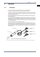
1-1 <1. General> 1. General 1.1 1 Features • 2 3 The sensor maintains stable characteristics over a prolonged period. It stabilizes in a initial time for electrolysis of approximately a half a day. The sensor has a structure less susceptible to the effects of deterioration in an electrolyte or contamination of the permeable membrane. Consequently, you can make precise measurements in a variety of processes.
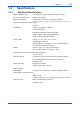
1.2 1.2.1 1-2 <1. General> Specifications Standard Specifications Object of Measurement: Concentration of oxygen dissolved in solution (water) Principle of Measurement: Galvanic-cell method Measurement Range: 0 to 20 ppm, 0 to 20 mg/l, or 0 to 100% (saturation) Note: The measurement range must be entered through the dissolved oxygen converter.
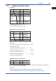
<1. General> 1.2.2 1-3 Model and Suffix Codes • DO Sensor 1 Suffix Code Model Option Code Description 2 DO sensor DO30G -NN – Membrane thickness Always -NN -03 -05 -10 -15 -20 Cable length 3m 5m 10m 15m 20m -PN -FK -FL Cable terminal 3 50 Mm -50 4 Pin terminal *1 Fork terminal M4 ring terminal *2 *1 Select pin terminal for DO402G, DO202, and FLXA21. When terminal box is used, select WTB10-DO3. *2 Used to connection to FLXA21. When terminal box is used, select WTB10-DO4.
1.2.3 1-4 <1. General> External View and Dimensions • Dissolved-oxygen sensor with pin terminals Unit: mm • Dissolved-oxygen sensor with fork terminals 11 12 14 13 15 16 11 12 14 13 15 16 Pin terminals Model and Suffix Codes DO30G - NN - 50 - 03 - PN DO30G - NN - 50 - 05 - PN DO30G - NN - 50 - 10 - PN DO30G - NN - 50 - 15 - PN DO30G - NN - 50 - 20 - PN Approx. 80 L 3 000 5 000 10 000 15 000 20 000 Weight (kg) Approx. 0.6 Approx. 0.8 Approx. 1.4 Approx. 2.0 Approx. 2.
2. 2-1 <2. Components and Their Functions> Components and Their Functions Sensor cable Carries the detected signal to the dissolved oxygen converter. The desired cable length can be chosen from 3, 5, 10, 15, or 20m. You can choose either pin-type, M4 ring-type or fork-type terminals.
Blank Page
3. 3-1 <3. Installing the Sensor and Connecting the Cable> Installing the Sensor and Connecting the Cable 1 2 3.1 3.1.1 Preparing for Installation 3 Removal of Parts for Transportation and Storage A cap to prevent the membrane from being damaged when transporting the sensor is mounted at the tip of the DO30G Dissolved Oxygen Sensor. When installing the sensor, remove this protective cap (See Appendix 1.). 3.1.
3.2 3.2.1 3-2 <3. Installing the Sensor and Connecting the Cable> Installation Normally, the DO30G Dissolved Oxygen Sensor is assembled into the PH8HG Guide Pipe, PB350G Angled Floating Ball Holder or DOX8HS Immersion Type Holder and submersed to the point best suited to obtain precise measurement results. This section explains how to select the measurement point and sensor holder.
3-3 <3. Installing the Sensor and Connecting the Cable> [PB350G Angled Floating Ball Holder] The fitting is designed to contain the sensor in a sphere that floats on a liquid. This fitting is immune to large variations in the liquid level. Since the wet part is smooth and less susceptible to catching flocs, the sensor does not trap rubbish that mixes in with the SUM (Related description: See Subsection 3.2.3).
3.2.3 3-4 <3. Installing the Sensor and Connecting the Cable> Asembling the Sensor in the Holder For details on how to assmble the sensor in the holder or fitting, see the appropriate instruction manual for each holder or fitting. CAUTION Exercise care not to contaminate or wet the tip of the sensor cable when assembling the sensor. If you will not begin wiring the sensor cable immediately, take the protective measures necessary to prevent the assembly from being damaged.
4. 4-1 <4. Maintenance> Maintenance This section describes the inspection and maintenance procedure applicable to just the dissolved oxygen sensor alone. For comprehensive inspection and tuning of the measuring system, such as calibration, see the DO402G Dissolved Oxygen Converter instruction manual (IM 12J05D02-01E), the DO202/FLXA21 2-wire Transmitter instruction manual (IM 12J05C01-01E/ IM 12A01A02-01E). 4.1 4.1.
4.2 4.2.1 4-2 <4. Maintenance> Inspection If Failure Occurs If the electrolyte and/or lead electrode within the sensor unit deteriorates and ultimately completes its service life, anomalies, such as the failure to make a span adjustment, will occur. This section deals especially with the inspection and service of the dissolved oxygen sensor needed if any anomaly is found in a detected signal.
<4. Maintenance> 4-3 (3) Completely drain the electrolyte within the sensor unit. Tilt the sensor tip downward and then use the syringe to force air into the inlet for refilling the electrolyte. Position the beaker so it will catch any of the electrolyte that drains through the gaps around the silver electrode. Inlet for refilling electrolyte 2 Needle (syringe needle) Sensor unit 3 Insert the syringe needle into the inlet for refilling electrolyte and force air inside.
4.2.2 <4. Maintenance> 4-4 Checking of RTD in the Sensor The resistance temperature detector (RTD) incorporated in the DO30G sensor is a Pt 1000 Ω RTD. This Pt 1000 Ω RTD indicates a resistance value of about 1097 Ω at 25 °C. Check the RTD by measuring the resistance value between conductors 11 (T1) and 12 (T2). If the resistance value differs greatly from the above value, the sensor must be replaced. 4.2.3 Judgment of Lead Electrode Fault If no failure is found in the checks in Subsections 4.2.
4-5 <4. Maintenance> Table 4.1 Items Contained in the DOX8A Maintenance Parts Kit Item Part No. Qty Remarks 50 ml Must be replaced periodically, either once every 6 to 8 months or if a span adjustment is not possible. Eight to 9 ml are consumed with each replacement. K9171HM 3 sets Normally, these parts must be replaced at the same time that the sensor is refilled with electrolyte.
Blank Page
A-1 Appendix 1. How to Remove the DO30G Membrane Protective Cap CAUTION A black rubber cap is attached to the tip of the DO30G to protect the membrane. Pulling off the cap forcefully causes a negative pressure inside the protective cap, because the protective cap sticks to the DO30G, and may stretch the membrane or damage it. Furthermore, removing the cap by twisting it may loosen the membrane assembly and affect the measurement results.
A-2 When using a stick or the like. (1) As shown in the figure 4, insert a stick or the like between the DO30G and protective cap. Be careful not to damage the DO30G main body. When an appropriate stick or the like is not available. (1) Hold the protective cap while holding the DO30G as shown in the figure 7. Stick or the like Protective with a diameter of cap 0.1 to 0.
Customer Maintenance Parts List Dissolved Oxygen Metering System DO30G Dissolved Oxygen Sensor 1 3 2 Model DO30G — Cable terminal Part No.
Customer Maintenance Parts List Model DOX8A-M*B Accessory for EXA DO 2 4 1 3 5 6 7 9 10 8 200 150 100 50 Item Part No.
Revision Record Title Manual No. : Model DO30G Dissolved Oxygen Sensor : IM 12J5B3-01E Edition Date Remark(s) 1st Nov. 1996 Newly published 2nd May 2007 Fully revised 3rd Mar. 2010 MS-code of DOX8A, DOX8W added to Section 1.2.2. CMPL 12J05B03-12E(2) added for DOX8A. 4th Apr. 2011 Over all revised. P. i, FLXA21 and DO202 manual no. added to documnents to be refered. P. 1-1, Stabilized time in a initial time for electrolysis modified. M4 ring terminal added to Figure 1.1. P.
Blank Page