
User Manual


IM 12J05C01-01E
Appendix 2-7
3/4
QIS 12J05C01-21E
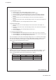
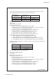
3.5 Galvanic Indication Check
Following Section 3.4, press the [ENT] key until the message display shows “GALVA.” Then
turn SW1 off. Change the current of the DC generator 1 and check the data display. The value
on the data display must be within the range shown in Table 3.
Table 3
Reference (A) Data Display (A)
10 10 ±0.06
30 30 ±0.1
50 50 ±0.2
3.6 Polarograph Indication Check
Press the [ENT] key until the message display shows “POLAR.1.” Then turn SW1 on. Change
the current of the DC generator 2 and check the data display. The value on the data display
must be within the range shown in Table 4.
Table 4
Reference (nA) Data Display (nA)
2 2 ±0.02
6 6 ±0.04
12 12 ±0.07
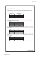
Press the [ENT] key. The message display will show “POLAR.2.” Change the current of the DC
generator 2 and check the data display. The value on the data display must be within the range
shown in Table 5.
Table 5
Reference (nA) Data Display (nA)
20 20 ±0.1
60 60 ±0.3
100 100 ±0.5
Press the [ENT] key. The message display will show “POLAR.3.” Change the current of the DC
generator 2 and check the data display. The value on the data display must be within the range
shown in Table 6.
Table 6
Reference (nA) Data Display (nA)
200 200 ±1
600 600 ±3
1000 1000 ±5
Press the [ENT] key until the message display shows “READY.” Press the [ENT] key again to
finish the tests.