
User Manual


IM 12J05C01-01E
8-1 Troubleshooting
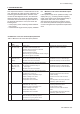
8-2. Measures in the case of failure (Error) detection
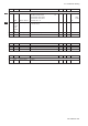
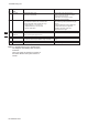
Table 8-1. Measures in the case of failure (Error) detection
Error Generation Error Content and Causes Measures
No. Mode
E 1 AIR.CAL mode Stability failure Eliminate the causes and press the
H20. CAL mode Even after an hour has elapsed, the (NO) key to perform re calibration.
measured value change does not decrease
within the set value of ppm
• Sensor temperature changes.
• Dissolved-oxygen of the calibration solution changes.
• The value of ppm is not suitable.
E 2 H20. CAL mode Zero error failure Clean the sensor membrane and
MAN.CAL mode The zero error exceeds the set range recalibrate. If the error is detected again,
(ZERO) • Dirt sticks to the sensor membrane. replace the electrolyte and the membrane.
• Membrane abnormality. Electrolyte degradation.
E 3 AIR.CAL mode Sensitivity failure Clean the sensor membrane and
H20. CAL mode The sensitivity exceeds the range of recalibrate. If the error is detected again,
MAN.CAL mode 1 - 1999 nA/ppm. replace the electrolyte and the membrane.
(SENS) • Dirt sticks to the sensor membrane.
• Membrane abnormality. Electrolyte degradation.
E 7 All modes Measured temperature failure (too high) Examine the temperatures of the
It exceeds 150.0 °C (302 °F). measuring solution and sensor and the
• Measuring solution temperature is high CODE 10 setting
• CODE 10 setting is not correct Examine the sensor cable connection
• Sensor cable wiring failure status.
• Temperature sensor has failed If the temperature sensor fails (abnormal
resistance), replace the sensor.
E 8 All modes Measured temperature failure (too low) Examine the temperatures of the
It falls below -20 °C (or -4 °F). measuring solution and sensor
• Measuring solution temperature is low and the CODE 10 setting.
• CODE 10 setting is not correct Examine the sensor cable connection
• Sensor cable wiring failure status.
• Temperature sensor has failed. If the temperature sensor fails (abnormal
resistance), replace the sensor.
E 9 All modes Input current failure Examine the setting for CODE 01, 022
It does not satisfy the following equation:
input current < 50 A for galvanic sensor
< 1200 nA for polarographic sensor
8. TROUBLESHOOTING
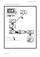
This chapter describes the countermeasures for fail-
ures, classifying the cases into three categories: dis-
solved-oxygen transmitter failure, detection of fail-
ure with the self-diagnosis function, and abnormal
measured values. The causes for abnormal meas-
ured values are not limited to equipment failures. If
an abnormal phenomenon occurs, first check the
following items:
• Is the property of the measuring solution different
from normal?
• Is the dissolved-oxygen sensor properly installed?
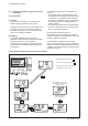
8-1. Measures in the case of transmitter opera-
tion failure
If the operation keys do not operate smoothly or the
display fails (e.g., a missing character segment),
repair of the printed circuit board (digital board) or
replacement with a new one is required.
After the printed circuit board is replaced, opera-
tion checks and parameter settings are necessary.
Contact Yokogawa and request board-replacement
work.