User’s Manual Model DO202G [Style: S2], DO202S [Style: S3] 2-wire Dissolved Oxygen Transmitter IM 12J05C01-01E IM 12J05C01-01E 4th Edition
PREFACE TABLE OF CONTENTS 1. INTRODUCTION AND GENERAL DESCRIPTION ......................................... 1-1 1-1. Instrument check .................................................................................... 1-1 1-2. Application ............................................................................................... 1-3 2. GENERAL SPECIFICATIONS......................................................................... 2-1 2-1. Specifications ...............................................
5-1-3. Manual pressure adjustment.................................................................................5-2 5-2-1. Output range..........................................................................................................5-3 5-2-2. Hold.......................................................................................................................5-4 5-2-3. Service..................................................................................................
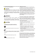
PREFACE DANGER Electric discharge The EXA analyzer contains devices that can be damaged by electrostatic discharge. When servicing this equipment, please observe proper procedures to prevent such damage. Replacement components should be shipped in conductive packaging. Repair work should be done at grounded workstations using grounded soldering irons and wrist straps to avoid electrostatic discharge.
The following safety symbols are used on the prod- Warranty and service uct as well as in this manual. Yokogawa products and parts are guaranteed free from defects in workmanship and material under normal use and service for a period of (typically) DANGER DANGER 12 months from the date of shipment from the manuThis symbol indicates that an operator must follow facturer.
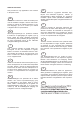
ATEX Documentation This procedure is only applicable to the countries in European Union. GB All instruction manuals for ATEX Ex related products are available in English, German and French. Should you require Ex related instructions in your local language, you are to contact your nearest Yokogawa office or representative. DK Alle brugervejledninger for produkter relateret til ATEX Ex er tilgængelige på engelsk, tysk og fransk.
SK PL CZ SLO LT H BG LV EST RO M IM 12J05C01-01E
Introduction 1-1 1. INTRODUCTION AND GENERAL DESCRIPTION The Yokogawa EXA 202 is a 2-wire transmitter designed for industrial process monitoring, measurement and control applications. This user’s manual contains the information needed to install, set up, operate and maintain the unit correctly. This manual also includes a basic troubleshooting guide to answer typical user questions. Yokogawa can not be responsible for the performance of the EXA analyzer if these instructions are not followed. 1-1.
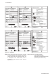
1-2 Introduction FISCO field device DISSOLVED OXYGEN TRANSMITTER MODEL SUFFIX MODEL SUFFIX DO202S-F 17.5VDC or 24VDC /380mA/5.32W /250mA/1.2W /380mA/5.32W OUTPUT PROFIBUS-PA Li=0 μH, Ci=220pF AMB.TEMP. -10 55°C AMB.TEMP. -10 55°C STYLE No. DISSOLVED OXYGEN TRANSMITTER MODEL SUFFIX R LR81741 C DO202S-B DO202S-F/-P FNICO field device DISSOLVED OXYGEN TRANSMITTER MODEL SUFFIX AMB.TEMP. 9 TO 32VDC FF-TYPE 113 -10 55°C SUPPLY OUTPUT AMB.TEMP. STYLE No.
Introduction 1-3 1-2. Application The EXA transmitter is intended to be used for continuous on-line measurement in industrial installations. The unit combines simple operation and microprocessor-based performance with advanced self-diagnostics and enhanced communications capability to meet the most advanced requirements. The measurement can be used as part of an automated process control system.
1-4 Introduction IM 12J05C01-01E
General Specifications 2-1 2. GENERAL SPECIFICATIONS Note: The transmitter contains a switched power supply. The transmitter requires a minimum power voltage in order to work correctly, which is dependant on the load. Please refer to figures 2-1 and 2-2 for the correct power supply - Temperature 1100.0 775.0 600.0 400.0 425.0 230.0 31.5 V (limit for IS version) 200.0 0.
2-2 General Specifications 2-2. Performance specifications L. Operation protection All three levels can be protected by a user programmable 3 digit password A. Performance in ppm mode - Linearity : ±0.05 ppm or ±0.8% FS, whichever is greater - Repeatability : ±0.05 ppm or ±0.8% FS, whichever is greater - Accuracy : ±0.05 ppm or ±0.8% FS, whichever is greater M. EMC Conformity standards EN 61326-1 Class A, Table 2 (For use in industrial locations) EN 61326-2-3 EN 61326-2-5 (pending) B.
General Specifications 2-3 Item CENELEC ATEX Entity CENELEC ATEX FISCO CENELEC ATEX Description CENELEC ATEX (KEMA) Intrinsically safe Approval Applicable standard: EN60079-0, EN50020 EN60079-26 Certificate: KEMA 07ATEX0054 X Ex ia IIC, Group: II, Category: 1G Temp. Class: T4, Amb. Temp.: -10 to 55°C Ui=24 V, Ii=250 mA, Pi=1.
2-4 General Specifications GB3836.13-1997 "Electrical apparatus for explosive gas atmospheres Part 13: Repair and overhaul for apparatus used in explosive gas atmospheres". GB3836.15-2000 "Electrical apparatus for explosive gas atmospheres- Part 15: Electrical installations in hazardous area (other than mines)" . GB3836.16-2006 "Electrical apparatus for explosive gas atmospheres- Part 16: lnspection and maintenance of electrical installation (other than mines)". mA mA-HART® communication A.
General Specifications 2-5 F-BUS interfaces from National Instruments (AT-FBUS, PCMIA-FBUS) M. Other control systems: YOKOGAWA PRM, DTM L. Hardware: 2-3.
General Specifications 2-6 2-4. Control Drawing of DO202S mA HART® Specification (IECEx) Intrinsically safe design IEC Ex standard Ex ia IIC : T4 for ambient temp. < 55°C T6 for ambient temp. < 40°C Ex ia or ib Certified safety barrier or pow er with R int=300 : (HART compatible) C ertificate nr. IECEx KEM 06.0055X (Dissolved O xygen -transmitter) DO202S 24 volts D C Nominal Supply Voltage. + + _ SENSOR (S) term inals 11-18 _ Uo = 31.
2-7 General Specifications 2-5. Control Drawing of DO202S mA HART® Specification (ATEX) Intrinsically safe design ATEX C lass I, D iv.1, G roup ABC D , T4 for ambient temp. < 55°C T6 for ambient temp. < 40°C C ertificate nr. K EM A 06A TEX 0224 X D O 202S transmitter A TEX A pproved safety barrier or pow er supply w ith R int = 300 : (HA R T compatible) 24 volts D C N ominal Supply V oltage. + + _ - G Sensor Fo r electrical data: see text belo w . terminals 11-18 M ax. cablelength: 60 mtr.
General Specifications 2-8 2-6. Control Drawing of DO202S mA HART® Specification (FM Intrinsically safe design) Intrinsically safe design FM Class I, Div.1, Group ABCD, T4 for ambient temp. < 55°C T6 for ambient temp. < 40°C DO202S transmitter FM Approved safety barrier or power supply with Rint = 300 : (HART compatible) 24 volts DC Nominal Supply Voltage. + + _ - G Sensor For electrical data: see text below. terminals 11-18 Max. cablelength: 60 mtr. Cable dia. : 3…12 mm.
2-9 General Specifications 2-7. Control Drawing of DO202S mA HART® Specification (FM Non-incendive design) N o n in c n e n d iv e d e s ig n F M C la s s I, D iv .2 , G ro u p A B C D , T 4 fo r a m b ie n t te m p . < 5 5 ° C T 6 fo r a m b ie n t te m p . < 4 0 ° C D O 2 0 2 S tra n s itte r F M A p p ro v e d p o w e r s u p p ly V o c ≤ 3 1 .5 V D C + + _ - G S ensor F o r e le c t r ic a l d a t a : se e t e x t b e lo w . te rm in a ls 1 1 -1 8 M a x . c a b le le n g th : 6 0 m tr.
General Specifications 2-10 2-8. Control Drawing of DO202S mA HART® Specification (CSA) Intrinsically safe design C S A E x ia C lass I, D iv.1, G roup A B C D , T 4 for am bient tem p. < 55°C T 6 for am bient tem p. < 40°C C S A certified safety barrier or pow er supply w ith R int= 300 : (H A R T compatible) D O 202S transm itter 24 volts D C N om inal Supply V oltage. + + _ G Fo r electrical d ata: see text belo w .
2-11 General Specifications 2-9. Control Drawing of DO202S FF/PB Specification (IECEx) Ex ia IIC T4 for ambient temp. d 55 qC Ui = 24 V or Ui = 17,5 V Ii = 250 mA Ii = 380 mA Pi = 1,2 W Pi = 5,32 W DO202S-F or DO202S-P + Safe area Apparatus + - I.S. interface Sensor Connections - I.S. certified Term inator I.S. certified Term inator + - Transm itter Safe area + - Transm itter Zone 0 or 1 Hazardous area x Sensor(s) are of a passive type to be regarded as 'simple apparatus'.
General Specifications 2-12 2-10. Control Drawing of DO202S FF/PB Specification (ATEX) Ex ia IIC T4 for ambient temp. d 55 qC Ui = 24 V or Ui = 17,5 V Ii = 250 mA Ii = 380 mA Pi = 1,2 W Pi = 5,32 W DO202S-F or DO202S-P + Safe area Apparatus + - I.S. interface Sensor Connections - I.S. certified Terminator I.S. certified Terminator + - Transmitter Safe area + - Transmitter Zone 0 or 1 Hazardous area x x x x Sensor(s) are of a passive type to be regarded as 'simple apparatus'.
2-13 General Specifications 2-11. Control Drawing of DO202S FF/PB Specification (FM Intrinsically safe Entity) FM Class I, DIV. 1, Group ABCD T4 for ambient temp. d 55 qC Sensor Connections Max. cablelength: 60 mtr. Cable dia. : 3…12 mm. DO202S-F or DO202S-P + FM Approved barrier Voc (Vt) d 24 V Ioc (It) d 250 mA Poc (Pt) d 1.2 W Ca t 220pF+ Ccable La t 0 H + Lcable + - Sensor Connections - I.S. certified Terminator I.S.
General Specifications 2-14 x The cable used to interconnect the devices needs to comply with the following parameters: Loop resistance R’: 15 … 150 Ω/km; Inductance per unit length L’: 0,4 … 1 mH/km Capacitance per unit length C’: 80 … 200 nF/km (C’ = C’ line/line + 0,5 C’ line/screen if both line are floating) (C’ = C’ line/line + C’ line/screen if the screen is connected to one line) Length of spur cable: max. 30 m Length of trunk cable: max. 1 km Length of splice : max.
2-15 General Specifications 2-12. Control Drawing of DO202S FF/PB Specification (FM Intrinsically safe FISCO) FM Class I, DIV. 1, Group ABCD T4 for ambient temp. d 55 qC Sensor Connections Max. cablelength: 60 mtr. Cable dia. : 3…12 mm. Sensor Connections DO202S-F or DO202S-P + FM Approved FISCO barrier Voc (Vt) d17,5 V Ioc (It) d380 mA Poc (Pt) d5,32 W + - - FM Approved Terminator R = 90..100Ω C = 0..2,2 μF FM Approved Terminator R = 90..100Ω C = 0..
General Specifications 2-16 x In each I.S. Fieldbus segment only one active source, normally the FM Approved FISCO barrier, is allowed to provide the necessary power for the Fieldbus system. All other equipment connected to the bus cable has to be passive (not providing energy to the system), except to a leakage current of 50μA for each connected device. Separately powered equipment needs a galvanic isolation to insure that the I.S. Fieldbus circuit remains passive.
2-17 General Specifications 2-13. Control Drawing of DO202S FF/PB Specification (FM Non-incendive Entity) FM Class I, DIV. 2, Group ABCD T4 for ambient temp. d 55 qC T6 for ambient temp. d 40 qC Sensor Connections Max. cablelength: 60 mtr. Cable dia.: 3…12 mm. Sensor Connections DO202S-B or DO202S-D + FM Approved Power Supply Voc d 32 VDC - FM Approved Terminator R = 90..100Ω C = 0..2,2 μF + - FM Approved Terminator R = 90..100Ω C = 0..
General Specifications 2-18 2-14. Control Drawing of DO202S FF/PB Specification (FM Non-incendive FNICO) FM Class I, DIV. 2, Group ABCD T4 for ambient temp. d 55 qC T6 for ambient temp. d 40 qC Sensor Connections Max. cablelength: 60 mtr. Cable dia.: 3…12 mm. Sensor Connections DO202S-B or DO202S-D FM Approved Power Supply Voc d 32 VDC + - + - FM Approved Terminator R = 90..100Ω C = 0..2,2 μF FM Approved Terminator R = 90..100Ω C = 0..
2-19 General Specifications 2-15. Control Drawing of DO202S FF/PB Specification (CSA) CSA Ex ia Class I, DIV. 1, Group ABCD T4 for ambient temp. d 55 qC Ui = 24 V Ii = 250 mA Pi = 1,2 W or Ui = 17,5 V Ii = 380 mA Pi = 5,32 W DO202S-F or DO202S-P + Safe area Apparatus + - I.S. interface Sensor Connections - I.S. certified Terminator I.S.
General Specifications 2-20 IM 12J05C01-01E
3-1 Installation and Wiring 3. INSTALLATION AND WIRING 3-1. Installation and dimensions The ambient temperature and humidity of the installation environment must be within the limits of the instrument specifications. (See chapter 2). 3-1-1. Installation site The EXA transmitter is weatherproof and can be installed inside or outside. It should, however, be installed as close as possible to the sensor to avoid long cable runs between sensor and transmitter.
Installation and Wiring 3-2 Unit: mm (inch) 18.5 (0.72) +1 0 +1 0 SPACING PANEL CUTOUT PANEL CUTOUT 3.5 (0.14) Fig. 3-2b. Panel mounting using two (2) self-tapping screws Pipe mounting (Vertical) 56 (2.20) Pipe mounting (Horizontal) 2-Ø6.5 (0.26) 200 (7.87) 4-Ø10 (0.4) 77 (3) 115 70 (4.5) (2.75) Nominal 50 A (O.D. Ø60.5 mm) (2 inch pipe) 4.eps Figure 3-3. Wall and pipe mounting diagram Figure 3-4.
3-3 Installation and Wiring 3-2. Wiring of power supply mA 3-2-1. General precautions Do not activate the power supply yet. First make sure that the DC-power supply is according to the specifications given. WARNING DO NOT USE ALTERNATING CURRENT OR MAINS POWER SUPPLY! ! The cable leading to the distributor (power supply) or safety barrier transports power to and output signal from the transmitter. Use a two conductor shielded cable with a size of at least 1.25 mm2 and an outside diameter of 6 to 12 mm.
Installation and Wiring 3-4 3-3-2. Wiring other galvanic sensors Consult the users manual for the color identification of the sensor cable. - The temperature sensor has two wires and must be connected to the terminal 11 and 12. - The measuring electrode: the cathode must be connected to terminal 13. - The reference electrode: the anode must be connected to terminal 15. - The overall shield of the cable must be connected to terminal 14 if there is one available. - Place the jumper in the GALVANIC position.
3-5 Installation and Wiring Extension cable may be purchased in bulk quantities, cut to length. Then it is necessary to terminate the cable as shown below. Termination procedure for WF10 cable. 1. Slide 3 cm of heat shrink tube (9 x 1.5) over the cable end to be terminated. 2. Strip 9 cm of the outer (black) insulating material, taking care not to cut or damage internal cores. 3 cm heat shrink 9 cm remove insulation Figure 3-9a. 3.
IM 12J05C01-01E
Operation: Display Functions and Settings 4-1 4. OPERATION; DISPLAY FUNCTIONS AND SETTING 4-1. Operator interface This section provides a survey of the operation of the EXA operator interface. The basic procedures for obtaining access to the three levels of operation are described briefly. For a step-by-step guide to data entry, refer to the relevant section of this user’s manual. Figure 4-1 shows the EXA operator interface.
4-2 Operation: Display Functions and Settings Main display Fail flag Message display TEMP.MAN FAIL YES NO ENT Key prompt flags Selection keys YES : Accept setting NO : Change setting YES NO Menu pointer flags MODE ppm ppb %sat CAL DISPLAY HOLD Commissioning function menu OUTPUT SET HOLD SERVICE Commissioning mode access key MODE ENT Adjustment keys > : Choose digit to adjust ^ : Adjust digit ENT : Confirm change Figure 4-1.
Operation: Display Functions and Settings 4-3 4-4. Display examples The following pages show the sequence of button presses and screens displayed when working in some standard configurations. More or less options will be made available by the configuration of some service codes, or by choices made in the commissioning menu. The following deviations are possible: Item marked is omitted when switched off in commissioning mode. * 4-5. Display function (default) TEMP.
5-1 Parameter Setting 5. PARAMETER SETTING 5-1. Maintenance mode Calibration Air Standard operation of the EXA instrument involves use of the Maintenance (or operating) mode to set up some of the parameters. Access to the Maintenance mode is available via the six keys that can be pressed through the flexible window in the instrument cover. Press the MODE key once to enter this dialog mode.
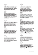
Parameter Setting 5-2 5-1-2. Manual temperature adjustment PPM PPB %SAT CAL DISPLAY HOLD MODE > Manual temperature Set using >, ,ENT keys. NO 2x TEMP.MAN YES YES NO ENT 5-1-3. Manual pressure adjustment PPM PPB %SAT CAL DISPLAY HOLD MODE NO 3x YES YES YES NO ENT IM 12J05C01-01E Calibration pressure Set using >, ,ENT keys. > > % sat process (process pressure) Set using >, ,ENT keys.
5-3 Parameter Setting 5-2. Commissioning mode In order to obtain peak performance from the EXA transmitter, you must set it up for each custom application. Refer to APPENDIX A-1-2 for standard configurations and options. mA Hold mA Output range: mA output is set as default to 0 - 20ppm. For enhanced resolution in more stable measuring processes, it may be desirable to select for example 5-10 ppm range. Service FAIL YES NO ENT YES NO This selection provides access to the service menu.
Parameter Setting 5-4 mA 5-2-2. HOLD TEMP.MAN FAIL YES NO ENT YES NO MODE ppm ppb %sat CAL DISPLAY HOLD OUTPUT SET HOLD SERVICE MODE ENT ENT HOLD ENT YES NO HOLD NO ENT YES NO YES NO YES NO HOLD NO YES ENT YES NO NO NO YES NO Set HOLD "fixed value" YES HOLD HOLD NO YES YES NO HOLD active last measured value.
5-5 Parameter Setting 5-2-3. SERVICE TEMP.MAN FAIL YES NO ENT YES NO MODE ppm ppb %sat CAL DISPLAY HOLD OUTPUT SET HOLD SERVICE MODE ENT mA Example: Service Code 01 Select Sensor Type for galvanic sensor Polarization voltage and sensitivity. Set using >, ,ENT keys.
Parameter Setting 5-6 5-3. Notes for guidance in the use of service coded settings Don't set or input service code numbers other than the code numbers defined in this manual. Setting an undefined service code may make the transmitter malfunction. When an undefined service code is input by some accident, push the MODE key and escape from the service level. 5-3-1. Parameter specific functions Code 1 *S.TYPE Select 0 for DO30G sensor or any other galvanic sensor.
5-7 Parameter Setting Code Display Function Parameter Specific functions 01 *S.TYPE Sensor type 04 *V.POL (Polarographic) Polarization Voltage *SENS Sensor sensitivity *SAL.TY Salinity comp. *[Cl-] NaCl conc. 05-09 Code Display Function Temperature Measuring Functions 10 *T.SENS Temp. Comp. 11 *T.UNIT Temp units 12 13 *T.ADJ *T.MAN Temp adjust Manual TC 14-19 Code Display Function Calibration Settings 20 *∆T.SEC Stabilization Step ∆Z.PPM ∆Z.PPB ∆Z.SAT ∆S.PPM (always PPM) 21 *Z.
Parameter Setting 5-8 mA 5-3-4. mA output functions Code 31 *OUTP.F Code 32 *BURN Code 35 *TABLE For the DO202 the output may be chosen as linear to input, or configured in a 21 point table to a particular linearization. Enable the table setup in code 31, and configure the table in code 35. Diagnostic error messages can signal a problem by sending the output signals upscale (21 mA) or downscale (3.6 mA when HART comm. non-used, 3.9 mA when HART comm. used).
5-9 Parameter Setting mA Code Display Output Functions 30 31 *OUTP.F Function 32 *BURN Burn function *TABLE *0% *5% *10% ... ... *95% *100% Output table for mA 33, 34 35 mA output functions 51 *P.MAN 52 *P.% *P.CAL *PASS 53 *Err.01 *Err.02 *Err.07 *Err.08 *Err.09 *Err.16 55 *CALL.M 56 *CALL .M *UNIT 57-59 X Not used Linear Table No burnout Burnout downscale Burnout upscale Pulse burnout Not used 0 1 0 1 2 3 Y Z Default values 0 Linear 0 No Burn.
Parameter Setting 5-10 5-3-6. Communication setup mA Code 60 *COMM. The settings should be adjusted to suit the communicating device connected to the output. The communication can be set to HART®. *ADDR. Select address 00 for point to point communication with 4-20mA transmission. Addresses 01 to 15 are used in multi-drop configuration (fixed 4mA output). mA Code 61 *HOUR *MINUT *SECND *YEAR *MONTH *DAY The clock/calendar for the logbook is set for current date and time as reference.
5-11 Parameter Setting mA mA Code Display Communication 60 *COMM. 61 62 63-69 *ADDR.
Calibration Procedure 6-1 6. CALIBRATION PROCEDURE Calibration of the dissolved oxygen analyzer is performed in the following situations: • When a new dissolved oxygen sensor is installed. • When the membrane is replaced and/or the electrolyte solution is replaced • When the sensor has been disassembled and reassembled for maintenance • When the measuring error after cleaning exceeds the acceptable deviation from reference method • When error message E16 indicates the need for maintenance 6-1.
6-2 Calibration Procedure 6-2. Calibration procedure using air calibration method 6-2-1. Preparation Move the sensor to a maintenance site and wash off any dirt on the membrane. Lightly wipe off any remaining water from the membrane with a soft tissue. Expose the sensor to the air in an environment where there is no temperature change and no wind (a convenient way to accomplish this environment is to place the sensor in an empty bucket).
Calibration Procedure 6-3 If both zero and span calibration are used, it is better to start with span calibration in spite of normal calibration sequence with analog instrumentation. Otherwise the sensor must be rinsed off carefully to prevent ingress of oxygen absorbing sulfite in the aerated water. Note: Zero calibration in the sodium sulfite solution takes a long time. Even after CAL.END prompt it is necessary to wait 40-50 minutes before zero adjustment can be made.
6-4 Calibration Procedure 6-4.
Calibration Procedure 6-5 6-4-3. Procedure for manual zero (offset) calibration TEMP.MAN FAIL MODE ppm ppb %sat CAL DISPLAY HOLD YES NO ENT OUTPUT SET HOLD SERVICE YES YES NO NO MODE ENT YES YES NO YES ENT ENT YES ENT NO ENT YES Select the flashing digit with the Increase its value by pressing the key. After briefly displaying WAIT, the display returns to the normal readout. key. When the correct value is displayed, press ENT to enter the change.
6-6 Calibration Procedure Table 6-1. Solubility of oxygen (mg/l) in water as a function of temperature & salinity (ISO 5814) Temp Solubility of oxygen in water in equilibrium with air Correction to be substracted for each degree of salinity expressed in grams per kilogram of total salts in water °C @101.325kPa[pO2] mg/l (ppm) [∆pO2] mg/l (ppm) 0 1 2 3 4 5 6 7 8 9 10 11 12 13 14 15 16 17 18 19 20 21 22 23 24 25 26 27 28 29 30 14.62 14.22 13.83 13.46 13.11 12.77 12.45 12.14 11.84 11.56 11.29 11.03 10.
Maintenance 7-1 7. MAINTENANCE It is important for maintaining the measurement accuracy of the EXA DO series of wire dissolvedoxygen metering system to perform inspection and maintenance at fixed intervals. It also serves to prevent problems from arising. This chapter describes daily inspection and maintenance for the purpose of maintaining system performance. 7-1. Overall dissolved-oxygen metering system 7-1-1. Inspection and maintenance to be implemented periodically Table 7-1.
8-1 Troubleshooting 8. TROUBLESHOOTING This chapter describes the countermeasures for failures, classifying the cases into three categories: dissolved-oxygen transmitter failure, detection of failure with the self-diagnosis function, and abnormal measured values. The causes for abnormal measured values are not limited to equipment failures.
Troubleshooting 8-2 Error Generation No. Mode E10 All modes mA mA Error content and Causes Measures EEPROM writing failure Electronic circuit failure Turn off the power and then turn it back on and check whether or not the system returns to normal. If the failure occurs again, contact Yokogawa to request repair. Accurately measure the temperature of the measuring solution (dissolved oxygen sensor).
9-1 Spare Parts 9. SPARE PARTS See Customer Maintenance Parts List. Figure 9-1.
Appendix 1-1 APPENDIX 1. USER SETTINGS A-1-1. User setting table FUNCTION mA mA mA SETTING DEFAULTS Parameter specific functions 01 *S.TYPE 1 *V.POL 0.675 *SENS 7.5 04 *SAL.TY 0 *[Cl-] 0 Temperature measuring functions 10 *T.SENS 1 11 *T.UNIT 0 12 *T.ADJ 13 *T.MAN 0 Calibration parameter functions 20 *∆T.SEC 60 *∆Z.PPM 0.1 *∆Z.PPB 1 *∆Z.SAT 1.0 *∆S.PPM 0.1 21 *∆Z.CAL 0 *∆Z.LIM 199.9 22 *ZERO 0 *SENS 7,5 mA outputs 31 *OUTP.F 0 32 *BURN 0 35 *TABLE 0 to 20 User Interface 50 *RET 1 51 *P.MAN 0 *P.% 101.
1-2 Appendix A-1-2 Configuration Checklist for DO202 mA mA Standard configuration Options Reference for change Measured variable(s) Primary inputs DO units Temperature unit DO and Temp ppm Celsius ppb. % saturation Fahrenheit code 56 code 11 mA Outputs Analog output Output linearization Burn out 4-20mA for ppm disabled disabled ppb or %sat code 56, 31 ppm, ppb or %sat code 35 burn low (3.
Appendix 1-3 mA A-1-4 Device description (DD) menu structure The Device Description (DD) is available from Yokogawa or the HART® foundation. An example is shown below of the ON LINE menu structure. This manual makes no attempt to explain the operation of the Hand Held Communicator (HHC). For detailed operating instructions, refer to the HHC instruction manual and the on-line help structure.
IM 12J05C01-01E
Appendix 2-1 APPENDIX 2. QUALITY INSPECTION A-2-1. DO202G 2-Wire Dissolved Oxygen Transmitter Quality Inspection Standards 1. DO202G Dissolved Oxygen Transmitter Scope This inspection standard applies to the DO202G Dissolved Oxygen Transmitter. 2. Inspection Items 2.1 2.2 2.3 * 2.4 * 2.5 Insulation resistance test Current output test Temperature indication check Galvanic indication check Polarograph indication check Note: Items marked with an asterisk (*) may only be confirmed by a test certificate.
2-2 Appendix 2/3 (2) Setting Password 070. a. Press the [>] key once. The data display will show “000” with the second digit of 0 flashing. b. Press the [] key seven times. The data display will show “070” with the second digit of 7 flashing. c. Press the [ENT] key. The message display will show “HIF.” d. Press the [YES] key. (3) Confirming the date and time. a. Press the [ENT] key. The data display will show the date in day, month, year format. b. Press the [ENT] key.
Appendix 2-3 3/3 Table 4 Reference (nA) Data Display (nA) 2 6 12 2 ±0.02 6 ±0.04 12 ±0.07 Press the [ENT] key. The message display will show “POLAR.2.” Change the current of the DC generator 2 and check the data display. The value on the data display must be within the range shown in Table 5. Table 5 Reference (nA) Data Display (nA) 20 60 100 20 ±0.1 60 ±0.3 100 ±0.5 Press the [ENT] key. The message display will show “POLAR.3.” Change the current of the DC generator 2and check the data display.
2-4 Appendix IM 12J05C01-01E
Appendix 2-5 A-2-2. DO202S 2-Wire Dissolved Oxygen Transmitter Quality Inspection Standards 1. DO202S Dissolved Oxygen Transmitter Scope This inspection standard applies to the DO202S Dissolved Oxygen Transmitter. 2. Inspection Items 2.1 * 2.2 2.3 2.4 * 2.5 * 2.6 Insulation resistance test Dielectric strength test Current output test Temperature indication check Galvanic indication check Polarograph indication check Note: Items marked with an asterisk (*) may only be confirmed by a test certificate.
2-6 Appendix 2/4 (1) Entering Service Code 87. a. Press the [ ] key. The message display will show “ OUTP.” b. Press the [NO] key twice. The message display will show “ SERV.” c. Press the [YES] key. The data display will show “00” with the first digit of 0 flashing. d. Press the [] key eight times. The data display will show “80” with the first digit of 8 flashing. e. Press the [>] key once. The data display will show “80” with the second digit of 0 flashing. f. Press the [] key seven times.
Appendix 2-7 3/4 3.5 Galvanic Indication Check Following Section 3.4, press the [ENT] key until the message display shows “GALVA.” Then turn SW1 off. Change the current of the DC generator 1 and check the data display. The value on the data display must be within the range shown in Table 3. Table 3 Reference (μA) 10 30 50 3.6 Data Display (μA) 10 ±0.06 30 ±0.1 50 ±0.2 Polarograph Indication Check Press the [ENT] key until the message display shows “POLAR.1.” Then turn SW1 on.
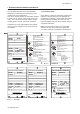
2-8 Appendix 4/4 DO202S SUPPLY + - TEMP G 11 12 16 + - + SH 15 13 18 14 GALV SENS POL SENS 17 SW1 + Shorting bar DC Ammeter 300 : - + DC Source + Decade Resistance Box - DC Generator 1 + - DC Generator 2 24 V DC Figure 1 Testing Circuit and Test Equipment QIS 12J05C01-21E IM 12J05C01-01E
Appendix 2-9 IM 12J05C01-01E
2-10 Appendix A-2-3. DO202G, DO202S 2-Wire Dissolved Oxygen Transmitter (Fieldbus Communication) Quality Inspection Standards 1. DO202G, DO202S Dissolved Oxygen Transmitter (Fieldbus Communication) Scope This inspection standard applies to the DO202G and DO202S Dissolved Oxygen Transmitters (Fieldbus specification). 2. Inspection Items 2.1 * 2.2 2.3 * 2.4 * 2.5 * 2.
Appendix 2-11 2/3 In this state, change the resistance value of the decade resistance box as shown in Table 1. The corresponding temperature indication must be within the range. Table 1 Reference Temperature (°C) –9 25 140 3.4 Resistance of Resistance Box (Ω) 99.6k 22k 653.8 Data Display (°C) –9 ±0.3 25 ±0.3 140 ±0.3 Galvanic Indication Check Turn on SW1. Set the sensor type to galvanic. Setting Service Code 01 to 0. a. Press the [ ] key. The message display will show “ SERV.” b. Press the [YES] key.
2-12 Appendix 3/3 i. Press the [ ] key. The instrument returns to the measurement mode. Set the display to nA current indication by following the steps below. a. Press the [MODE] key. The message display will show “CALIB.” b. Press the [NO] key once. The message display will show “DISP.” c. Press the [YES] key once. The message display will show temperature indication. d. Press the [NO] key five times. The message display will show nA current indication.
Appendix 2-13 IM 12J05C01-01E
2-14 Appendix A-2-4. DO202G, DO202S 2-Wire Dissolved Oxygen Transmitter (Profibus Communication) Quality Inspection Standards 1. DO202G, DO202S Dissolved Oxygen Transmitter (Profibus Communication) Scope This inspection standard applies to the DO202G and DO202S Dissolved Oxygen Transmitters (Profibus specification). 2. Inspection Items 2.1 * 2.2 2.3 * 2.4 * 2.5 * 2.
Appendix 2-15 2/3 In this state, change the resistance value of the decade resistance box as shown in Table 1. The corresponding temperature indication must be within the range. Table 1 Reference Temperature (°C) –9 25 140 3.4 Resistance of Resistance Box (Ω) 99.6k 22k 653.8 Data Display (°C) –9 ±0.3 25 ±0.3 140 ±0.3 Galvanic Indication Check Turn on SW1. Set the sensor type to galvanic. Setting Service Code 01 to 0. a. Press the [ ] key. The message display will show “ SERV.” b. Press the [YES] key.
2-16 Appendix 3/3 i. Press the [ ] key. The instrument returns to the measurement mode. Set the display to nA current indication by following the steps below. a. Press the [MODE] key. The message display will show “CALIB.” b. Press the [NO] key once. The message display will show “DISP.” c. Press the [YES] key once. The message display will show temperature indication. d. Press the [NO] key five times. The message display will show nA current indication.
Appendix 2-17 IM 12J05C01-01E
Customer Maintenance Parts List Model DO202G [Style: S2] Disolved Oxygen Transmitter 9 14 8 3 10 11 5 4 6,7 2 Item 1 2 3 4 5 6 7 8 *9 *10 11 12 13 *14 13 12 1 Part No.
Pipe/Wall Mounting Hardware (Option Code : /U) 1 1 Panel Mounting Hardware (Option Code : /SCT) 2 Hood to sun protection 3 Option Code : /H /H2 4 (Option Code : /PM) Item 1 2 3 4 CMPL 12J05C01-02E Parts No. K9171SS K9311BT K9311KA K9311KG K9660JA Qty 1 1 1 1 1 Description Universal Mount Set (/U) Tag Plate (/SCT) Fitting Assembly (/PM) Hood Assembly (/H) Hood Assembly (/H2) 2nd Edition : Aug.
Customer Maintenance Parts List Model DO202S [Style: S3] Disolved Oxygen Transmitter 9 14 8 3 10 11 5 4 6 2 Item 1 2 12 1 Part No.
Pipe/Wall Mounting Hardware (Option Code : /U) 1 1 Panel Mounting Hardware (Option Code : /SCT) 2 Hood to sun protection 3 Option Code : /H /H2 4 (Option Code : /PM) Item 1 2 3 4 CMPL 12J05C01-23E Parts No. K9171SS K9311BT K9311KA K9311KG K9660JA Qty 1 1 1 1 1 Description Universal Mount Set (/U) Tag Plate (/SCT) Fitting Assembly (/PM) Hood Assembly (/H) Hood Assembly (/H2) 2nd Edition : Nov.
Revision Record Manual Title : Model DO202G [Style: S2], DO202S [Style: S3] 2-wire Dissolved Oxygen Transmitter Manual Number : IM 12J05C01-01E Edition Date Remark (s) 1st Mar. 2007 Newly published 2nd Oct. 2007 PREFACE-1, Some of warning description modified; P. 1-1, Some of nameplate in Figure 1-1 changed; P. 1-2, Some of nameplate in Figure 1-2 changed; P. 2-2, EN 61000-3-3 deleted from "M. Regulatory compliance"; P. 2-3, Certificate no.
User’s Manual Model DO202G [Style: S2], DO202S [Style: S3] 2-Wire Dissolved Oxygen Transmitter Supplement Thank you for selecting our Model DO202G [Style: S2] and/or DO202S [Style: S3] 2-Wire Dissolved Oxygen Transmitter. User's Manual, IM 12J05C01-01E, 4th Edition, supplied with the product, some revisions/additions have been made. Please replace the corresponding pages in your copy with the attached, revised pages. Revisions: - PREFACE, "How to dispose the batteries" added.
PREFACE DANGER Electric discharge The EXA analyzer contains devices that can be damaged by electrostatic discharge. When servicing this equipment, please observe proper procedures to prevent such damage. Replacement components should be shipped in conductive packaging. Repair work should be done at grounded workstations using grounded soldering irons and wrist straps to avoid electrostatic discharge.
2-2 General Specifications 2-2. Performance specifications L. Operation protection All three levels can be protected by a user programmable 3 digit password A. Performance in ppm mode - Linearity : ±0.05 ppm or ±0.8% FS, whichever is greater - Repeatability : ±0.05 ppm or ±0.8% FS, whichever is greater - Accuracy : ±0.05 ppm or ±0.8% FS, whichever is greater M.