
Instruction Manual
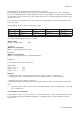
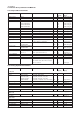
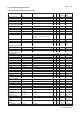


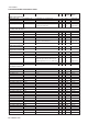
Table Of Contents
- 1. Introduction
- 2. Safety Precautions
- 3. FOUNDATION FIELDBUS
- 3-1 About Foundation Fieldbus
- 3-2 Getting started
- 3-3 Configuration
- 3-4 In-process operation
- 3-5 Device status
- 3-6 List of parameters for each block of the EXA
- 3-7 Application setting and change of basic parameters
- 3-8 Operation of each parameter in failure mode
- 4. PROFIBUS
- APPENDIX 1. LINK MASTER FUNCTIONS
- Revision Record
- Supplement

4-8 Profibus
IM 12A00A01-61E
4-4. Function block parameters and Methods
4-4-1. Physical Block Parameters
Parameter Default Alternatives R/W Slot, Index Data Type
(byte,bit) (bytes)
Software revision “R3.01” R 0,24 visible string (16)
Hardware revision “R3.01” R 0,25 visible string (16)
Device manufacturer ID 37hex (Yokogawa) R 0,26 unsigned16 (2)
Device ID PH202 “5945430850” R 0,27 visible string (16)
SC202 “5945430851” R 0,27 visible string (16)
ISC202 “5945430852” R 0,27 visible string (16)
DO202 “5945430853” R 0,27 visible string (16)
Device serial number “00000000U9313508” (example) R 0,28 visible string (16)
Diagnosis for details see .gsd file R 0,29 bit string (4)
Diagnosis extension for details see .gsd file R 0,30 bit string (6)
Diagnosis mask R 0,31 bit string (4)
Diagnosis mask extension R 0,32 bit string (6)
Device certifiacation R 0,33 visible string (32)
Write locking Write enable (2457) Write disable (0) R/W 0,34 unsigned16 (2)
Factory reset 0 factory reset (1), warm start (2506),
reset bus address to 126 (2712) R/W 0,35 unsigned16 (2)
Descriptor YOKOGAWA PROFIBUS
-PA ANALYZER R/W 0,36 visible string (32)
Device message YOKOGAWA PROFIBUS
-PA ANALYZER R/W 0,37 visible string (32)
Device install date “” R 0,38 visible string (16)
Ident number selector manufacturer specific
ident no (1) profile specific ident number (0) R/W 0,40 unsigned8 (1)
Device configuration “” R 0,52 visible string (32)
Init state run (2) R/W 0,53 unsigned8 (1)
Device state run (2) R/W 0,54 unsigned8 (1)
Global status 0 bit0 - failure, bit1 - maintenance requested,
bit2 - function check, bit3 - limits exceeded,
bit4~15 - reserved R 0,55 bit string (2)
4-4-2. Analog Input Block Parameters
Parameter Default Alternatives R/W Slot, Index Data Type
(byte,bit) (bytes)
AI1, AI2, AI3
Static Revision No. R 1,17 unsigned16 (2)
Channel PH202: pH(284) Temp (298), ORP/rH(305)
SC202: SC1(284) Temp (292), SC2(303), Conc(302)
ISC202: SC1(284) Temp (292), SC2(303), Conc(302)
DO202: DO(284) Temp (299), %Sat(306), sensor current(305) R/W 1,30 unsigned16 (2)
Linearization type Non linearization (0) R/W 1,29 unsigned 8 (1)
Unit R 1,28 DS-36 (11)
Decimal point 1 R/W 1,28 DS-36 (11)
Filter Time Const R/W 1,32 float (4)
Process Value Scale
Lower Value R/W 1,27 float[2] (8)
Upper Value R/W 1,27 float[2] (8)
Output Scale
Lower Value R/W 1,28 DS-36 (11)
Upper Value R/W 1,28 DS-36 (11)
Output Limits
Upper Limit Alarm Maximum of float R/W 1,37 float (4)
Upper Limit Warning Maximum of float R/W 1,39 float (4)
Lower Limit Warning Minimum of float R/W 1,41 float (4)
Lower Limit Alarm Minimum of float R/W 1,43 float (4)
Limit Hysteresis 0.5 % R/W 1,35 float (4)