
Instruction Manual
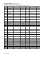
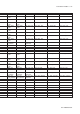
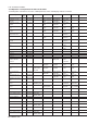
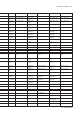
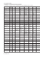

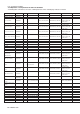
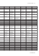
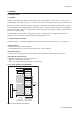
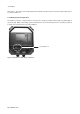
Table Of Contents
- 1. Introduction
- 2. Safety Precautions
- 3. FOUNDATION FIELDBUS
- 3-1 About Foundation Fieldbus
- 3-2 Getting started
- 3-3 Configuration
- 3-4 In-process operation
- 3-5 Device status
- 3-6 List of parameters for each block of the EXA
- 3-7 Application setting and change of basic parameters
- 3-8 Operation of each parameter in failure mode
- 4. PROFIBUS
- APPENDIX 1. LINK MASTER FUNCTIONS
- Revision Record
- Supplement
4-2 Profibus
IM 12A00A01-61E
Node adress, block tags and contained parameters within a function block are structured in the EXA device
as shown in figure 4.1.
4-1-4 Wiring System Configuration
The number of devices (<32) that can be connected to a single bus and the cable length vary depending on
system design. When constructing systems, both the basic and overall design must be carefully considered
to allow device performance to be fully exhibited.
Figure 4.2 Internal view of EXA wiring compartment
See Figure 4.4.