
Instruction Manual
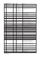
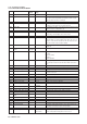
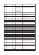
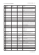

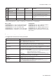
Table Of Contents
- 1. Introduction
- 2. Safety Precautions
- 3. FOUNDATION FIELDBUS
- 3-1 About Foundation Fieldbus
- 3-2 Getting started
- 3-3 Configuration
- 3-4 In-process operation
- 3-5 Device status
- 3-6 List of parameters for each block of the EXA
- 3-7 Application setting and change of basic parameters
- 3-8 Operation of each parameter in failure mode
- 4. PROFIBUS
- APPENDIX 1. LINK MASTER FUNCTIONS
- Revision Record
- Supplement

IM 12A00A01-61E
3-38 Foundation Fieldbus
3-6-3-3 Transducer Block ISC202
Index Parameter name Factory Valid Description
Default Range
2000 BLOCK HEADER TAG: “TB” General information about thefunction block
2001 ST_REV - - The revision level of the static data associated with the function
block. The revision value will be incremented each time a static
parameter value in the block is changed
2002 TAG_DESC “ “ The user description of the intended application of the block
2003 STRATEGY 1 The strategy field can be used to identify grouping of blocks.
This data is not checked or processed by the block
2004 ALERT_KEY 1 The identification number of the plant unit. This information may be
used in the host for sorting alarms, etc.
2005 MODE_BLK AUTO The actual, target, permitted, and normal modes of the block
2006 BLOCK_ERR - This parameter reflects the error status associated with a block. It
is a bit-string, so that multiple errors can be shown
2007 UPDATE_EVT - The alert is generated by any change to the static data.
2008 BLOCK_ALM - The block alarm is used for all configuration error, hardware
connection failure or system problems in the block. The cause of
the alert is entered in the subcode field. The first alert to become
active will set Active status in Status attribute.
2009 TRANSDUCER_DIRECTORY A directory that specifies the number and starting indices of the
transducers.
2010 TRANSDUCER Conductivity conductivity Conductivity transducer block
_TYPE Transmitter
2011 XD_ERROR - The error code in transducer:
No failure,
Electronics failure,
I/O failure,
Mechanical failure
2012 COLLECTION_DIRECTORY - A directory that specifies the number, starting indices and DD item
Ids of the data collection in each transducer within a transducer
block
2013 PRIMARY_VALUE_TYPE conductivity, conductivity Type of measurement represented by primary value
2014 PRIMARY_VALUE - 0 to 2 S/cm Primary value of the instrument is Conductivity
2015 PRIMARY_VALUE_RANGE 0 to 2 S/cm 0 to 2 S/cm The range of the instrument (can not change)
2016 SENSOR_CONST 1.88 0.2 to 19.99 cm
-1
The conductivity cell has a specific cell constant determined by the
dimensions of the cell
2017 CAL_POINT_HI 1.999 0 to 2 S/cm Highest calibration point
2018 CAL_POINT_LO 0 0 to 2 S/cm Lower calibration point
2019 CAL_MIN_SPAN 0,0001 > 0,0001 S/cm Minimum span between two calibration points
2020 SENSOR_CAL_METHOD - 1point, 2point not used
2021 SENSOR_CAL_DATE - till 2104 Date the sensor was last calibrated
2022 SECONDARY_VALUE - -20 to 140 ºC , Temperature value
0 to 280ºF
2023 SECONDARY_VALUE_UNIT ºC ºC, ºF Temperature unit
2024 SENSOR_TEMP automatic automatic auto when a temperature element is available
2025 SENSOR_TEMP_MAN_VALUE - - No manual temp. value possible. Always automatic
2026 SENSOR_TYPE _TEMP NTC30K Pt1000, NTC30k Temperature element used:
2027 SENSOR_CONNECTION_ 2 2 Only 2-wire connections supported
TEMP
2028 SENSOR_TYPE_COND toroidal toroidal Non contacting toroidal sensor.
2029 SENSOR_OHMS - Actual cell resistance
2030 XD_MAN_ID “ “
2031 TEMPERATURE_COEFF 2.1 0 to 3.5%/ºC (%/ºF) Process temperature compensation factor
2032 CONCENTRATION - Conductivity combined with temperature can be directly related to the
concentration. Concentraion isexpressed in percentage
2033 TERTIARY_VALUE - 0 to 2 S/cm Second compensated conductivity value
2034 REFERENCE_TEMPERATURE 25 0 to 100 ºC Conductivity can be process compensated to a standard
(32 to 212ºF) reference temperature. Mostly 20ºC or 25ºC is used