
Instruction Manual

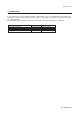
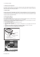
Table Of Contents
- 1. Introduction
- 2. Safety Precautions
- 3. FOUNDATION FIELDBUS
- 3-1 About Foundation Fieldbus
- 3-2 Getting started
- 3-3 Configuration
- 3-4 In-process operation
- 3-5 Device status
- 3-6 List of parameters for each block of the EXA
- 3-7 Application setting and change of basic parameters
- 3-8 Operation of each parameter in failure mode
- 4. PROFIBUS
- APPENDIX 1. LINK MASTER FUNCTIONS
- Revision Record
- Supplement
IM 12A00A01-61E
Introduction 1-1
1. IntroductIon
In the standard user’s manual delivered with the 202 analyzer all necessary information about HART-com-
munication is included. This manual describes only those topics that are required for operation of the field-
bus communications.
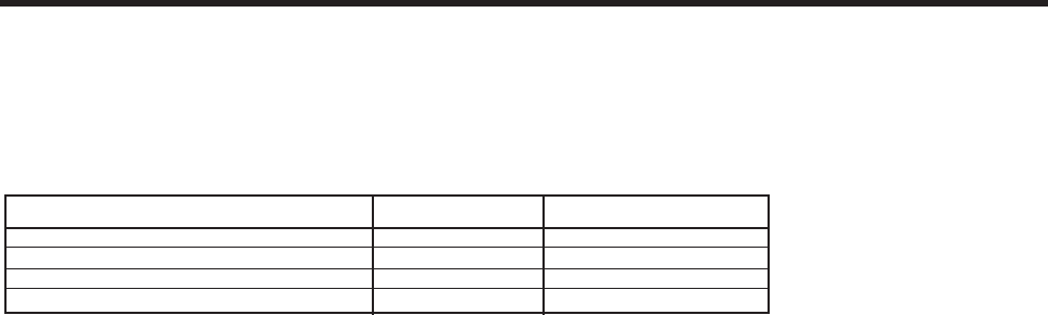
For information about instruments related to the EXA202, refer to the following User’s Manuals.
Manual Name IM No. Instruments mentioned
2-wire pH/ORP Transmitter IM 12B07D02-01E PH202G, PH202S
2-wire Conductivity or Resistivity Transmitter IM 12D08B02-01E SC202G, SC202S
2-wire Inductive Conductivity Transmitter IM 12D06A03-01E ISC202G, ISC202S
2-wire Dissolved Oxygen Transmitter IM 12J05C01-01E DO202G, DO202S
T01.EPS