
Instruction Manual
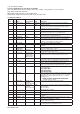
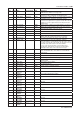
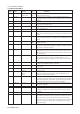
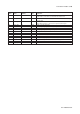
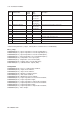
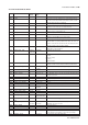
Table Of Contents
- 1. Introduction
- 2. Safety Precautions
- 3. FOUNDATION FIELDBUS
- 3-1 About Foundation Fieldbus
- 3-2 Getting started
- 3-3 Configuration
- 3-4 In-process operation
- 3-5 Device status
- 3-6 List of parameters for each block of the EXA
- 3-7 Application setting and change of basic parameters
- 3-8 Operation of each parameter in failure mode
- 4. PROFIBUS
- APPENDIX 1. LINK MASTER FUNCTIONS
- Revision Record
- Supplement

IM 12A00A01-61E
Foundation Fieldbus 3-33
3-33
Index Parameter name Factory Valid Description
Default Range
2029 SECONDARY_VALUE_UNIT °C °C, °F Temperature unit
2030 SENSOR_TEMP_COMP automatic Off, manual, Select off when no temperature compensation is required.
automatic Select manual when no temperature element is available and the
temperature is stable and select auto when a temperature element
is available
pH: man + auto
orp: off + auto
2031 SENSOR_TEMP_MAN_VALUE 25 -30 to 140°C, manual temperature value
-20 to 280°F
2032 SENSOR_TYPE_TEMP Pt1000 Pt1000, Pt100, Temperature element used:
5k1, 3kBalco,
8k55, 350,
NTC10k, 6k8
2033 SENSOR_CONNECTION 2 2 Only 2-wire connections supported
_TEMP
2034 TERTIARY_VALUE_TYPE None None, ORP, rH When a metal electrode is used in combination with a glass and
reference electrode one has the possibility to measure a tertiary
value:
2035 TERTIARY_VALUE - -1500 to 1500 mV, The third value is expresed in mV or rH units
0 to 55 rH
2036 TERTIARY_VALUE_RANGE -1500 -1500 to 1500 mV, The high and low range limits for the tertiary value.
to 1500 0 to 55 rH
2037 TERTIARY_ZERO 0 -120 to 120mV Redox offset can be set in mV.
2038 GLASS_IMPEDANCE - 1MΩ to 2 GΩ (HI) Value that indicates the state of the glass membrane.
1kΩ to 1MΩ (LO) Depending on the jumper setting the range is set to High or Low.
2039 REFERENCE_IMPEDANCE - 1MΩ to 2 GΩ (HI) Value that indicates the state of the reference system.
1kΩ to 1MΩ (LO) Depending on the jumper setting the range is set to High or Low.
2040 ALARM_SUM -
2041 DEV_ALARM - Device Alarm is used to give the status of the transmitter. Device_
status in RB displays the device Alarms.
2042 LOGBOOK1_RESET - Reset the pointer to the first (oldest) event in logbook 1.
2043 LOGBOOK1_EVENT - Event whereto the pointer is referenced. When parameter is read,
the pointer is increased by one.
2044 LOGBOOK2_RESET - Reset the pointer to the first (oldest) event in logbook 2.
2045 LOGBOOK2_EVENT - Event whereto the pointer is referenced. When parameter is read,
the pointer is increased by one.
2046 LOGBOOK_CONFIG - Per event one can decide whether it should be logged and in which
logbook (1 or 2) it should be logged.
2047 TEST_1 - Service parameter
.... - 2048 to 2058 are, like 2047 and 2059, service parameters
2059 TEST_13 - Service parameter
2060 STABLE_TIME 5 5.0 to 30.0 Stability criteria used during automatic calibration.
2061 STABLE_VALUE 0.02 0.01 to 1.0 Stability criteria used during automatic calibration.
2062 CALL_MAINT_TIME_
COUNTDOWN 250 1 to 250 The remaining days till maintenance is required.
2063 CALL_MAINT_TIME_RELOAD 250 1 to 250 The interval of the maintenance timer.
2064
INPUT_1_IMPEDANCE_LO_LIM
1.00E6 100.0 to 1.0E9 The low limit of the input 1 impedance.
2065
INPUT_1_IMPEDANCE_HI_LIM
1.00E9 100.0 to 1.0E9 The high limit of the input 1 impedance.
2066
INPUT_2_IMPEDANCE_LO_LIM
100 100.0 to 1.0E9 The low limit of the input 2 impedance.
2067
INPUT_2_IMPEDANCE_HI_LIM
200000 100.0 to 1.0E9 The high limit of the input 2 impedance.
2068 BUFFER1_ID 4 0 to 9 The ID of buffer one, used during automatic calibration.
2069 BUFFER1 4.0 -2.0 to 16.0 The first user defined calibration buffer.
2070 BUFFER2_ID 7 0 to 9 The ID of buffer two, used during automatic calibration.
2071 BUFFER2 7.0 -2.0 to 16.0 The second user defined calibration buffer.
2072 BUFFER3_ID 9 0 to 9 The ID of buffer three, used during automatic calibration.
2073 BUFFER3 9.0 -2.0 to 16.0 The third user defined calibration buffer.
2074
TEMPERATURE_COEFFICIENT
0.0 -1.0 to 1.0 The temperature coefficient of the primary value.
-100.0 to 100.0