
Instruction Manual


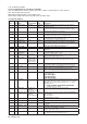

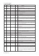


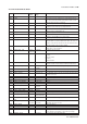
Table Of Contents
- 1. Introduction
- 2. Safety Precautions
- 3. FOUNDATION FIELDBUS
- 3-1 About Foundation Fieldbus
- 3-2 Getting started
- 3-3 Configuration
- 3-4 In-process operation
- 3-5 Device status
- 3-6 List of parameters for each block of the EXA
- 3-7 Application setting and change of basic parameters
- 3-8 Operation of each parameter in failure mode
- 4. PROFIBUS
- APPENDIX 1. LINK MASTER FUNCTIONS
- Revision Record
- Supplement

IM 12A00A01-61E
3-30 Foundation Fieldbus
Relative Parameter Factory Write
Index Name Default Mode Explanation
0 Block Header TAG: “AI1” or Block Tag Information on this block such as Block Tag, DD
“AI2” or “AI3” = O/S Revision, Execution Time etc.
1 ST_REV – – The revision level of the static data associated with the function block. The
revision value will be incremented each time a static parameter value in the block
is changed.
2 TAG_DESC (blank) AUTO The user description of the intended application of the block.
3 STRATEGY 1 AUTO The strategy field can be used to identify grouping of blocks. This data is not
checked or processed by the block.
4 ALERT_KEY 1 AUTO The identification number of the plant unit. This information may be used in the
host for sorting alarms, etc.
5 MODE_BLK AUTO AUTO The actual, target, permitted, and normal modes of the block.
6 BLOCK_ERR – – This parameter reflects the error status associated with the hardware or software
components associated with a block. It is a bit string, so that multiple errors may
be shown.
7 PV – – Either the primary analog value for use in executing the function, or a process
value associated with it. May also be calculated from the READBACK value of an
AO block.
8 OUT – Value= The primary analog value calculated as a result of
MAN executing the function.
9 SIMULATE Disable AUTO Allows the transducer analog input or output to the block to be manually supplied
when simulate is enabled. When simulation is disabled, the simulate value and
status track the actual value and status.
10 XD_SCALE – O/S The high and low scale values, engineering units
code, and number of digits to the right of the decimal point used with the value
obtained from the transducer for a specified channel. Refer to Table 3.18 to 3.21
for the unit available.
11 OUT_SCALE – O/S The high and low scale values, engineering units
code, and number of digits to the right of the decimal point to be used in
displaying the OUT parameter and parameters which have the same scaling as
OUT.
12 GRANT_DENY 0 AUTO Options for controlling access of host computers and local control panels to
operating, tuning and alarm parameters of the block.
13 IO_OPTS 0 O/S Options which the user may select to alter input and output block processing
bit6: Low cutoff
14 STATUS_OPTS Propagate Fault O/S Options which the user may select in the block
Forward processing of status
15 CHANNEL AI1: 1 O/S The number of the logical hardware channel that is
AI2: 2 connected to this I/O block. This information defines the transducer to be
AI3: 3 used going to or from the physical world.
16 L_TYPE Direct (1) MAN Deterines if the values passed by the transducer time of order block to the AI
block may be used directly (Direct) or if the value is in different units and must be
converted linearly (Indirect), or with square root (Ind Sqr Root), using the input
range defined by the transducer and the associated output range.
17 LOW_CUT Linear: 0% AUTO Sets low cut point of output. This low cut value become available by setting
“Low cutoff“ to “IO_OPTS“.
18 PV_FTIME 2sec AUTO Time constant of a single exponential filter for the PV, in seconds.
19 FIELD_VAL – – Raw value of the field device in percent of thePV range, with a status reflecting
the Transducer condition, before signal characterization (L_TYPE) or filtering
(PV_FTIME).
20 UPDATE_EVT – – This alert is generated by any change to the static data.
21 BLOCK_ALM – – The block alarm is used for all configuration, hardware, connection failure or
system problems in the block. The cause of the alert is entered in the subcode
field. The first alert to become active will set the Active status in the Status
attribute. As soon as the Unreported status is cleared by the alert reporting task,
another block alert may be reported without clearing the Active status, if the
subcode has changed.
3-6-2 Analog input Block