
Instruction Manual
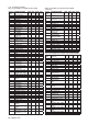
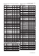
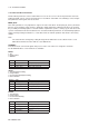
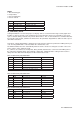
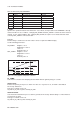
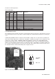
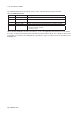
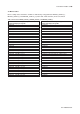
Table Of Contents
- 1. Introduction
- 2. Safety Precautions
- 3. FOUNDATION FIELDBUS
- 3-1 About Foundation Fieldbus
- 3-2 Getting started
- 3-3 Configuration
- 3-4 In-process operation
- 3-5 Device status
- 3-6 List of parameters for each block of the EXA
- 3-7 Application setting and change of basic parameters
- 3-8 Operation of each parameter in failure mode
- 4. PROFIBUS
- APPENDIX 1. LINK MASTER FUNCTIONS
- Revision Record
- Supplement

IM 12A00A01-61E
Foundation Fieldbus 3-23
3-23
An alert has following structure:
Table 3.22 Alert Object
Subindex
Parameter Name Explanation
Analog
Alert
Discrete
Alert
Update
Alert
1 1 1 Block Index Index of block from which alert is generated
2 2 2 Alert Key Alert Key copied from the block
3 3 3 Standard Type Type of the alert
4 4 4 Mfr Type Alert Name identified by manufacturer specific DD
5 5 5 Message Type Reason of alert notification
6 6 6 Priority Priority of the alarm
7 7 7 Time Stamp Time when this alert is first detected
8 8 Subcode Enumerated cause of this alert
9 9 Value Value of referenced data
10 10 Relative Index Relative index of referenced data
8 Static Revision Value of static revision (ST_REV) of the block
11 11 9 Unit Index Unit code of referenced data
3-4-3 Simulation Function
The simulation function simulates the input of a function block and lets it operate as if the data was received
from the transducer block. It is possible to conduct testing for the downstream function blocks or alarm proc-
esses.
A SIMULATE_ENABLE switch is mounted on the FF PCB assembly. This is to prevent the accidental oper-
ation of this function. When this is switched on, simulation is enabled. (See Figure 3.13) To initiate the same
action from a remote terminal, if REMOTE LOOP TEST SWITCH is written to the SIM_ENABLE_MSG
parameter (index 1044) of the resource block, the resulting action is the same as is taken when the above
switch is on. Note that this parameter value is lost when the power is turned OFF. In simulation enabled sta-
tus, an alarm is generated from the resource block, and other device alarms will be masked; for this reason
the simulation must be disabled immediately after using this function.
Simulation
Enable
Not used
1
2
off on
Figure 3.13 SIMULATE_ENABLE Switch Position
FF PCB
assembly