
Instruction Manual
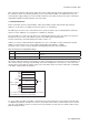


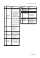

Table Of Contents
- 1. Introduction
- 2. Safety Precautions
- 3. FOUNDATION FIELDBUS
- 3-1 About Foundation Fieldbus
- 3-2 Getting started
- 3-3 Configuration
- 3-4 In-process operation
- 3-5 Device status
- 3-6 List of parameters for each block of the EXA
- 3-7 Application setting and change of basic parameters
- 3-8 Operation of each parameter in failure mode
- 4. PROFIBUS
- APPENDIX 1. LINK MASTER FUNCTIONS
- Revision Record
- Supplement
IM 12A00A01-61E
Foundation Fieldbus 3-13
3-13
3-3-6-2 Trend Object
It is possible to set the parameter so that the function block automatically transmits Trend. The EXA has
ten Trend objects: eight for trends of analog paramenters and two for discrete parameters. A single Trend
object specifies the trend of one parameter.
Each Trend object has the parameters listed in Table 3.9. The first four parameters are the items to be set.
Before writing to a Trend object, it is necessary to release the WRITE_LOCK parameter.
Table 3.9 Parameters for Trend Objects
Sub-index Parameters Description
1 Block Index Sets the leading index of the function block that takes a trend.
2 Parameter Relative
Index
Sets the index of parameters taking a trend by a value relative to the beginning of the function
block. In the EXA AI block, the following three types of trends are possible.
7: PV
8: OUT
19: FIELD_VAL
3 Sample Type Specifies how trends are taken. Choose one of the following 2 types:
1:Sampled upon execution of a function block.
2:The average value is sampled.
4 Sample Interval Specifies sampling intervals in units of 1/32 ms. Set the integer multiple of the function block
execution cycle.
5 Last Update The last sampling time.
6 to 21 List of Status 16 samples of status.
21 to 37 List of Samples 16 samples of data.
Ten trend objects are factory-set as shown Table 3.10.
Table 3.10 Trend Object are Factory-Set
Index Parameters Factory Settings
32000 to 32007 TREND_FLT.1 to TREND_FLT.8 Not used.
32008 to 32009 TREND_DIS.1 to TREND_DIS.2 Not used.
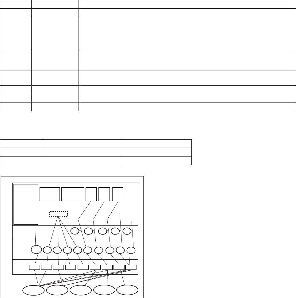
SMIB
(System
Management
Information
Base)
NMIB
(Network
Management
Information
Base)
AI3
OUT
AI1
OUT
AI2
OUT
FBOD
Alert
Trend
VCR
DLSAP
DLCEP
Fieldbus Cable
0xF8 0xF3 0xF4 0xF7
0xF9
0x20 0x220x21
0x07
#5
Device 3
#10
#1 #4
#3
#2
Resource
block
Transducer
block
Host 1
Host 2
Device 1
Device 2
Link
object
#1
#2
#3 #4
#5
#6
#7
#8
#9
Figure 3.10 Example of Default Configuration