User’s Manual EXA 202 Fieldbus Communication IM 12A00A01-61E IM 12A00A01-61E 2nd Edition
TABLE OF CONTENTS 1. Introduction................................................................................................... 1-1 2. Safety Precautions..................................................................................... 2-1 3. FOUNDATION FIELDBUS . ................................................................................. 3-1 3-1 About Foundation Fieldbus............................................................................... 3-1 3-1-1 Outline..........................
-8 Operation of each parameter in failure mode................................................. 3-46 3-8-1 3-8-2 3-8-3 3-8-4 Operation Operation Operation Operation of of of of each each each each parameter parameter parameter parameter in in in in failure failure failure failure mode mode mode mode PH202.....................................................3-46 SC202.....................................................3-48 ISC202....................................................3-50 DO202........
Introduction 1-1 1. Introduction In the standard user’s manual delivered with the 202 analyzer all necessary information about HART-communication is included. This manual describes only those topics that are required for operation of the fieldbus communications. For information about instruments related to the EXA202, refer to the following User’s Manuals.
Safety Precautions 2-1 2. Safety Precautions • For the protection and safety of the operator and the instrument or the system including the instrument, please be sure to follow the instructions on safety described in this manual when handling this instrument. In case the instrument is handled in contradiction to these instructions, Yokogawa does not guarantee safety.
Foundation Fieldbus 3-1 3. FOUNDATION FIELDBUS 3-1 About Foundation Fieldbus 3-1-1 Outline Fieldbus is a bi-directional digital communication protocol for field devices, which offers an advancement implementation technologies for process control systems and is widely employed by numerous field devices. EXA Series Fieldbus communication type employs the specification standardized by The Fieldbus Foundation, and provides interoperability between Yokogawa devices and those produced by other manufacturers.
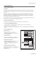
3-2 Foundation Fieldbus 3-1-4 Wiring System Configuration The number of devices that can be connected to a single bus and the cable length vary depending on system design. When constructing systems, both the basic and overall design must be carefully considered to allow device performance to be fully exhibited. 3-2 Getting started Fieldbus is fully dependent upon digital communication protocol and differs in operation from conventional 4 to 20 mA transmission communication protocol.
Foundation Fieldbus 3-3 3-2-1-2. Cables, terminals and glands The EXA202 is equipped with terminals suitable for the connection of finished cables in the size range: 0.13 to 2.5 mm (26 to 14 AWG). The glands will form a tight seal on cables with an outside diameter in the range of 6 to 12 mm (0.24 to 0.47 inches). The following instruments are required for use with Fieldbus devices: • Power supply Fieldbus requires a dedicated power supply.
3-4 Foundation Fieldbus 3-2-2 Host Setting To activate Fieldbus, the following settings are required for the host. IMPORTANT Do not turn off the power immediately after setting. When the parameters are saved to the EEPROM, the redundant processing is executed for an improvement of reliability. If the power is turned off within 60 seconds after setting is made, the modified parameters are not saved and the settings may return to the original values. Table 3.
Foundation Fieldbus 3-5 3-2-4 Integration of DD If the host supports DD (Device Description), the DD of the EXA needs to be installed. Check if host has the following directory under its default DD directory. 594543\DEV_TYPE (594543 is the manufacturer number of Yokogawa Electric Corporation, and DEV_TYPE is the EXA device number, respectively.) If this directory is not found, DD of EXA has not been included. Create the above directory and copy the DD file (0m0n.ffo,0m0n.
3-6 Foundation Fieldbus 3-3 Configuration This chapter contains information on how to adapt the function and performance of the EXA to suit specific applications. Because two or more devices are connected to Fieldbus, settings including the requirements of all devices need to be determined. Practically, the following steps must be taken. (1) Network design Determines the devices to be connected to Fieldbus and checks the capacity of the power supply.
Foundation Fieldbus � 3-7 ��� First, check the capacity of the power supply. The power supply capacity must be greater than the sum of the maximum current consumed by all devices to be connected to Fieldbus. The maximum current consumed (power supply voltage 9 to 32 V) for EXA is 26.0 mA. The cable must have the spur in a minimum length with terminators installed at both ends of the trunk. 3-3-2 Network Definition Before connection of devices with Fieldbus, define the Fieldbus network.
3-8 Foundation Fieldbus Table 3.3 Operation Parameter Values of the EXA to be Set to LM Devices Symbol Parameters Description and Settings V (ST) Slot-Time Indicates the time necessary for immediate reply of the device. Unit of time is in octets (256 µs). Set maximum specification for all devices. For EXA, set a value of 4 or greater. V (MID) Minimum-Inter-PDU-Delay Minimum value of communication data intervals. Unit of time is in octets (256 µs). Set the maximum specification for all devices.
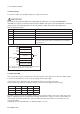
Foundation Fieldbus ���� 3-9 Macrocycle (Control Period) LI100 OUT IN LIC100 BKCAL_IN CAS_IN BKCAL_OUT FIC100 FC100 IN FI100 OUT BKCAL_IN BKCAL_OUT Communication Schedule Unscheduled Communication Scheduled Communication Figure 3.8 Function Block Schedule and Communication Schedule When the macrocycle is set to more than 4 seconds, set the following intervals to be more than 1% of the macrocycle.
3-10 Foundation Fieldbus 3-3-5 Communication Setting To set the communication function, it is necessary to change the database residing in SM-VFD. 3-3-5-1 VCR Setting Set VCR (Virtual Communication Relationship), which specifies the called party for communication and resources. EXA has 33 VCRs whose application can be changed, except for the first VCR, which is used for management. EXA has VCRs of 3 types: Publisher(-Subscriber) VCR Publisher-Subscriber VCR’s are designed to link Function Blocks.
3-11 Foundation Fieldbus ����� Table 3.5 VCR Static Entry Subindex 1 2 3 Parameter Description FasArTypeAndRole I ndicates the type and role of communication (VCR). The following 3 types are used for EXA. 0x32: Server (Responds to requests from host.) 0x44: Source (Transmits alarm or trend.) 0x66: Publisher (Sends AI block output to other blocks.) Sets the local address to specify VCR in EXA. A range of 0x20 to 0xF7 in hexadecimal.
3-12 Foundation Fieldbus Table 3.
3-13 Foundation Fieldbus ����� 3-3-6-2 Trend Object It is possible to set the parameter so that the function block automatically transmits Trend. The EXA has ten Trend objects: eight for trends of analog paramenters and two for discrete parameters. A single Trend object specifies the trend of one parameter. Each Trend object has the parameters listed in Table 3.9. The first four parameters are the items to be set. Before writing to a Trend object, it is necessary to release the WRITE_LOCK parameter.
3-14 Foundation Fieldbus 3-3-��������������� 6-3 View Object This is the object to form groups of parameters in a block. One advantage of forming groups of parameters is the reduction of load for data transaction. The EXA has four View Objects for each Resource block, Transducer block and AI1, AI2, AI3 function block, and each View Object has the parameters listed in Table 3.12 to 3.14. Table 3.
3-15 Foundation Fieldbus ����� Table 3.13 View Object for Resource Block Relative Parameter Mnemonic Index 1 ST_REV Table 3.
3-16 Foundation Fieldbus Table 3.
3-17 Foundation Fieldbus ����� Table 3.
3-18 Foundation Fieldbus 3-3-6-4 Function Block Parameters Function block parameters can be read from the host or can be set. For a list of the parameters of blocks held by the EXA, refer to “3-6 List of parameters for each block of the EXA”. The following is a list of important parameters with a guide how to set them. MODE_BLK: This mode parameter is very important as it gives the state of the block. In O/S (Out_Of_Service) mode the block is out of operation.
3-19 Foundation Fieldbus ����� DO202 1: Dissolved Oxygen, 2: Temperature, 3: Percent Saturation, 4: Sensor Current Channel Value Unit 1 primary_value primary_value_range.units 2 secondary_value secondary_value_unit 3 percent_saturation % 4 sensor_current nA XD_SCALE/OUT_SCALE: Scaling information is used for two purposes. Display devices need to know the range for bar graphs and trending, as well as the units code.
3-20 Foundation Fieldbus Table 3.21 Unit Index by XD_SCALE DO202 Channel FF parameters Service code XD_SCALE.UNITS 2 FF2030 SC11 (set to 0) °C (1001) 2 FF2030 SC11 (set to 1) °F (1002) 1 FF2016 SC56 (set to 0) ppm (1423) 1 FF2016 SC56 (set to 1) ppb (1424) 1 FF2016 SC56 (set to 2) % (1342) 3 - Default % % (1342) 4 - Default nA nA (1213) L_TYPE: Specifies the operation function of the AI block. If set to “Direct”, the input delivered to CHANNEL is directly reflected on OUT.
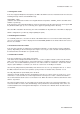
3-21 Foundation Fieldbus ����� Equations: (channel value - EU@0%) FIELD_VAL = 100 (EU@100% - EU@0%) [XD_SCALE] Direct: PV = channel value Indirect: PV = EU@0% + FIELD_VAL (EU@100% - EU@0%) 100 Ind Sqr Root: PV = EU@0% + [OUT_SCALE] √(FIELD_VAL) (EU@100% - EU@0%) [OUT_SCALE] 100 CHANNEL Simulate SIMULATE Mode Convert L_TYPE XD_SCALE OUT_SCALE Cutoff LOW_CUT Filter PV_FTIME PV Output OUT FIELD_VAL Alarms HI/LO IM 12A00A01-61E
3-22 Foundation Fieldbus 3-4 In-process operation This chapter describes the procedure performed when changing the operation of the function block of the EXA in process. 3-4-1 Mode Transition When the function block mode is changed to Out_Of_Service, the function block pauses and a block alarm is issued. When the function block mode is changed to Manual, the function block suspends updating of output values. In this case alone, it is possible to write a value to the OUT parameter of the block for output.
3-23 Foundation Fieldbus ����� An alert has following structure: Table 3.
3-24 Foundation Fieldbus The SIMULATE parameter of AI block consists of the elements listed in Table 3.23 below. Table 3.23 SIMULATE Parameter Sub-index Parameters Description 1 Simulate Status Sets the data status to be simulated. 2 Simulate Value Sets the value of the data to be simulated. 3 Transducer Status Displays the data status from the transducer block. It cannot be changed. 4 Transducer Value Displays the data value from the transducer block. It cannot be changed.
3-25 Foundation Fieldbus ����� 3-5 Device status Device setting status and failures of EXA are indicated by using parameter DEVICE_STATUS_1, DEVICE_STATUS_2 and DEVICE_STATUS_3 (index 1045, 1046 and 1047) in Resource Block. Table 3.24 Contents of DEVICE_STATUS_1, DEVICE_STATUS_2 and DEVICE_STATUS_3 DEVICE_STATUS_1 Hexadecimal Display through DD 0x80000000 0x40000000 0x20000000 0x10000000 0x08000000 0x04000000 0x02000000 0x01000000 0x00800000 Sim.
3-26 Foundation Fieldbus DEVICE_STATUS_2 PH202 Hexadecimal Display through DD 0x80000000 0x40000000 0x20000000 0x10000000 0x08000000 0x04000000 0x02000000 0x01000000 0x00800000 0x00400000 0x00200000 0x00100000 0x00080000 FF interface checksum error 0x00040000 EXA checksum error (E21) 0x00020000 Internal communication failure 0x00010000 FF interface eeprom failure 0x00008000 EXA eeprom failure (E20) 0x00004000 mismatch between FF- and EXA parameter 0x00002000 0x00001000 0x00000800 0x00000400 0x00000200 0x00
3-27 Foundation Fieldbus ����� DEVICE_STATUS_2 ISC202 Hexadecimal Display through DD 0x80000000 0x40000000 0x20000000 0x10000000 0x08000000 0x04000000 0x02000000 0x01000000 0x00800000 0x00400000 0x00200000 0x00100000 0x00080000 FF interface checksum error 0x00040000 EXA checksum error (E21) 0x00020000 Hart communication failure 0x00010000 FF interface eeprom failure 0x00008000 EXA eeprom failure (E20) 0x00004000 mismatch between FF- and EXA parameter 0x00002000 0x00001000 0x00000800 0x00000400 0x00000200 0
3-28 Foundation Fieldbus 3-6 List of parameters for each block of the EXA Note: The Write Mode column contains the modes in which each parameter is write enabled. O/S: Write enabled in O/S mode. MAN: Write enabled in Man mode and O/S mode. AUTO: Write enabled in Auto mode, Man mode, and O/S mode.
3-29 Foundation Fieldbus ����� Relative Parameter Index Index Name 25 1025 FREE_TIME Factory Default 0 Write Mode – 26 1026 SHED_RCAS 640000 (2S) AUTO 27 1027 SHED_ROUT 640000 (2S) AUTO 28 1028 FAULT_STATE 1 – 29 1029 SET_FSTATE 1 AUTO 30 1030 CLR_FSTATE 1 AUTO 31 1031 MAX_NOTIFY 3 – Writing a Clear to this parameter will clear the device fail-safe state if the field condition, if any, has cleared. Maximum number of unconfirmed notify messages possible.
3-30 Foundation Fieldbus 3-6-2 Analog input Block Relative Index Parameter Name Factory Default Write Mode 0 Block Header TAG: “AI1” or Block Tag Information on this block such as Block Tag, DD “AI2” or “AI3” = O/S – – The revision level of the static data associated with the function block. The 1 ST_REV Explanation Revision, Execution Time etc. revision value will be incremented each time a static parameter value in the block is changed.
3-31 Foundation Fieldbus ����� Relative Index Parameter Name Factory Default Write Mode 22 ALARM_SUM – – The current alert status, unacknowledged states, unreported states, and 23 ACK_OPTION 0xFFFF AUTO Selection of whether alarms associated with the block will be automatically 24 ALARM_HYS 0.5% AUTO Amount the PV must return within the alarm limits before the alarm condition 25 HI_HI_PRI 0 AUTO Priority of the high high alarm.
3-32 Foundation Fieldbus 3-6-3 Transducer Block 3-6-3-1 Transducer Block PH202 Index Parameter name Factory Default Valid Range 2000 BLOCK HEADER TAG: “TB” 2001 ST_REV - Description General information about the function block - The revision level of the static data associated with the function block. The revision value will be incremented each time a static parameter value in the block is changed.
3-33 Foundation Fieldbus ����� Index Parameter name Factory Default Valid Range Description 2029 SECONDARY_VALUE_UNIT °C °C, °F Temperature unit 2030 SENSOR_TEMP_COMP Off, manual, Select off when no temperature compensation is required.
3-34 Foundation Fieldbus Index Parameter name 2075 Factory Default passcode_maintenance 0 2076 passcode_commissioning 0 Valid Range Description 0, 111, 333, 777, Passcode used to protect the maintenance menu. 888, 123, 957, 331, 546, 847 0, 111, 333, 777, 2077 passcode_service 0 Passcode used to protect the commissioning menu. 888, 123, 957, 331, 546, 847 0, 111, 333, 777, Passcode used to protect the service menu.
3-35 Foundation Fieldbus ����� 3-6-3-2 Transducer Block SC202 Index Parameter name Factory Valid Default Range 2000 BLOCK HEADER TAG: “TB” 2001 ST_REV - Description General information about thefunction block - The revision level of the static data associated with the function block.
3-36 Foundation Fieldbus Index Parameter name 2034 REFERENCE_ Factory Default 25 Valid Range Description 0 to 100 ºC, Conductivity can be process compensated to a standard TEMPERATURE 32 to 212 ºF reference temperature. Mostly 20ºC or 25ºC is used 2035 COMP_METHOD NaCl NaCl, TC, matrix Method of process temp.
3-37 Foundation Fieldbus ����� * Enumerated parameters (4 bytes, 32 bits) where each bit can be set individually.
3-38 Foundation Fieldbus 3-6-3-3 Transducer Block ISC202 Index Parameter name Factory Default Valid Range 2000 BLOCK HEADER TAG: “TB” 2001 ST_REV - Description General information about thefunction block - The revision level of the static data associated with the function block.
3-39 Foundation Fieldbus ����� Index Parameter name Factory Default Valid Range Description 2035 COMP_METHOD NaCl NaCl, TC, matrix Method of process temperature compensation for the primary value 2036 COMP_MATRIX_SEL H2SO4 H2SO4, 0 -100ºC, 0 - 5%, When matrix compensation is required one can H2SO4, 0 -100ºC, 2.5 - 25%, HCl, 0 - 60ºC, 0.5 - 5%, make a selection out of 8 predefined matrices and one user definable matrix HNO3, 0 - 80ºC, 0.5 - 5% HNO3, 0 -80ºC, 2.
3-40 Foundation Fieldbus * Enumerated parameters (4 bytes, 32 bits) where each bit can be set individually.
Foundation Fieldbus 3-41 3-6-3-4 Transducer Block DO202 Index Parameter Factory Valid Range Description Name Default 2000 BLK_DATA TAG: “TB” 2001 ST_REV - General information about the function block - The revision level of the static data associated with the function block. The revision value will be incremented each time a static parameter value in the block is changed.
3-42 Foundation Fieldbus Index Parameter Factory Valid Range Description Name Default 2023 AMP_ZERO_STABILIZE - 0 to 50 ppm Stability criteria used during automatic zero calibration. _VALUE 0 to 1999 ppb 0 to 600 % 2024 SALINITY 0 0 to 99.9 ppt Salinity value of the process liquid that can be used to 2025 BAR_PRESSURE 101.3 0.
Foundation Fieldbus 3-43 Index Parameter 2054 Name Default CONFIGURATION* Factory Valid Range Description 2055 ALARM_SUM - 2056 DEV_ALARM - 2057 TEST_1 - Instrument specific configuration Device Alarm is used to give the status of the transmitter. Device_status in RB displays the device Alarms. ….
3-44 Foundation Fieldbus 3-7-2 Setting and change of basic parameters This section describes the procedure taken to set and change the parameters for each block. Obtaining access to each parameter differs depending on the configuration system used. For details, refer to the instruction manual for each configuration system. Access the block mode (MODE_BLK) of each block. Set the Target of block mode (MODE_BLK) to Auto, Man or O/S (*Note 2) according to the Write Mode of the parameter to be set or changed.
Foundation Fieldbus 3-45 With the EXA, the channel values are displayed on the display indicator, independant of the scaling in the AI blocks. (2) Setting the output mode Access the L_TYPE parameter. Set the output mode. 1: Direct (Sensor output value) 2: Indirect (Linear output value) 3: IndirectSQRT (Square root extraction output value) (3) Setting the damping time constant Access the PV_FTIME parameter. Set the damping time (in seconds).
3-46 Foundation Fieldbus 3-8 Operation of each parameter in failure mode 3-8-1 Operation of each parameter in failure mode PH202 • Following table summarizes the value of EXA parameters when LCD display indicates an Alarm. EXA display E9 E12 E7 E8 E5.1 E4.1 E5.2 E4.
Foundation Fieldbus 3-47 transducer block transducer block transducer block AI1 (channel = 1) AI2 (channel = 2) PV.status SV.status TV.status OUT.status OUT.status BAD, SENS BAD, SENS_FAIL _FAIL BAD, SENS_FAIL AI3 (channel = 3) OUT.
3-48 Foundation Fieldbus 3-8-2 Operation of each parameter in failure mode SC202 • Following table summarizes the value of EXA parameters when LCD display indicates an Alarm. error description resource block transducer block BLOCK_ERR BLOCK_ERR XD_ERROR PV.
Foundation Fieldbus 3-49 channel = 1 (AI1) channel = 2 (AI2) channel = 3 (AI3) channel = 4 OUT.status OUT.status OUT.status BAD, SENS_FAIL BAD, SENS_FAIL BAD, SENS_FAIL BAD, SENS_FAIL BAD, SENS_FAIL BAD, SENS_FAIL BAD, SENS_FAIL BAD, SENS_FAIL BAD, SENS_FAIL BAD, SENS_FAIL BAD, NON_SPECIFIC TV.status CONCENTRATION.status OUT.
3-50 Foundation Fieldbus 3-8-3 Operation of each parameter in failure mode ISC202 • Following table summarizes the value of EXA parameters when LCD display indicates an Alarm. error description EXA dev_alarm resource block transducer block display BLOCK_ERR BLOCK_ERR XD_ERROR PV.status SV.
Foundation Fieldbus 3-51 TV.status CONCENTRATION.status BAD, SENS BAD, SENS_FAIL _FAIL BAD, SENS BAD, SENS_FAIL _FAIL BAD, SENS BAD, SENS_FAIL _FAIL BAD, SENS BAD, SENS_FAIL _FAIL BAD, NON BAD, NON_SPECIFIC _SPECIFIC BAD, CONFIG BAD, CONFIG_ERR _ERR BAD, CONFIG BAD, CONFIG_ERR channel = 1 (AI1) channel = 2 (AI2) channel = 3 (AI3) channel = 4 OUT.status OUT.
3-52 Foundation Fieldbus 3-8-4 Operation of each parameter in failure mode DO202 • Following table summarizes the value of EXA parameters when LCD display indicates an Alarm. error description EXA resource block transducer block DO value dev_alarm eror BLOCK_ERR BLOCK_ERR calibration not stable E1 0x80000000 XD_ERROR zero out of limits 0x40000000 E2 INPUT_FAILURE_ERR 0x20000000 0x10000000 S_LIMIT_NON E3 temp.
Foundation Fieldbus 3-53 Temperature value Saturation percentage Cell current AI1 (channel = 1) AI2 (channel = 2) AI3 (channel = 3) SV.status TV.status QV.status OUT.status OUT.status OUT.
Profibus 4-1 4. PROFIBUS 4-1. About Profibus 4-1-1 Outline Profibus is a bi-directional digital communication protocol for field devices, which offers an advancement implementation technologies for process control systems and is widely employed by numerous field devices. EXA Series Profibus communication type employs the specification standardized by the Profibus organisation, and provides interoperability between Yokogawa devices and those produced by other manufacturers.
4-2 Profibus Node adress, block tags and contained parameters within a function block are structured in the EXA device as shown in figure 4.1. 4-1-4 Wiring System Configuration The number of devices (<32) that can be connected to a single bus and the cable length vary depending on system design. When constructing systems, both the basic and overall design must be carefully considered to allow device performance to be fully exhibited. See Figure 4.4. Figure 4.
Profibus 4-3 Sensor cable gland Profibus cable gland Grounding terminal (connect to safety ground, only if power supply is not grounded) Figure 4.3 Glands to be used for cabling Figure 4.5 Gland connection Figure 4.
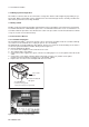
4-4 Profibus 4-2. Preparation The EXA 202 Profibus is provided with two cable glands. The first is used for the electrode wiring as the other is used for the power wiring shown in figure 4.3. To 1. 2. 3. 4. open the EXA 202 for wiring: Loosen the four frontplate screws and remove the cover. The terminal strip is now visible. Connect the power supply according figure 4.4. Use the gland on the left for this cable. Connect the sensor input, using the gland on the right (see figure 4.3). Switch on the power.
Profibus 4-5 4-3. GETTING STARTED Profibus is fully dependent upon digital communication protocol (EN 50170 Volume 2 and IEC 61158 for IS areas, Profibus PA) and differs in operation from the conventional 4 to 20 mA transmission communication protocol. It is recommended that novice users use field devices in accordance with the procedures described in this section. The procedures assume that field devices will be set up on a bench or an instrument shop.
4-6 Profibus IMPORTANT Connecting a Profibus configuration tool to a loop with its existing host may cause communication data scrambles resulting in a functional disorder or a system failure. 4-3-2 Host Setting To activate Profibus, the following settings are required for the host. IMPORTANT Do not turn off the power immediately after setting. When the parameters are saved to the EEPROM, the redundant processing is executed for an improvement of reliability.
Profibus 4-7 Beforehandone must configure which information will be exchanged. According with the Profibus-PA Profile 3.01, there are two kinds of configurations possible. The Identifier byte (or short identifier) and the Extended Identifier Format (or long identifier). The EXA supports both kinds of configurations. The user can choose either “Analog Input (short)” or “Analog Input (long)” and will end up with the same result. The function blocks of the EXA are in a specific order.
4-8 Profibus 4-4. Function block parameters and Methods 4-4-1. Physical Block Parameters Parameter Default Alternatives R/W Slot, Index Data Type (byte,bit) (bytes) Software revision “R3.01” R 0,24 visible string (16) Hardware revision “R3.
Profibus 4-9 4-4-3. Transducer block parameters 4-4-3-1.
4-10 Profibus 4-4-3-1. Transducer block parameters PH202 (continued) Parameter Default Reference impedance circuit Reference impedance compensation Ref. impedance exceeds low limit (E4.2) Ref. impedance exceeds high limit (E5.2) Temp. sensor open (E7) Temp. sensor shorted (E8) Primary value exceeds limits (E9) Calibration timer expired (E16) Passcode Configuration Passcode Maintenance Alternatives Low(0) Unit R/W Slot, Index Data Type (byte,bit) (bytes) High(1) R/W 4, 167 (2.
Profibus 4-11 4-4-3-1.
4-12 Profibus 4-4-3-2.
Profibus 4-13 4-4-3-2. Function Block Parameters SC202 (continued) Parameter Default Alternatives Unit R/W Slot, Index Data Type (byte,bit) (bytes) Calibration Parameters Nominal cell constant 0.1 0.005~50 1/cm R/W 4, 30 float (4) Calibrated cell constant 0.1 0.005~50 1/cm R 4, 89 float (4) Calibration method Not calibrated(0) 1 point(107), 2 point(108) R/W 4, 34 unsigned8 (1) Diagnostic Settings Polarisation check Enabled(1) Disable(0) 4, 151(2.
4-14 Profibus 4-4-3-2. Function Block Parameters SC202 (continued) Parameter Default Solution Solution Solution Solution Solution Solution Solution Solution Solution Solution Solution Solution Solution Solution Solution Solution Solution Solution Solution 2 2 2 2 3 3 3 3 3 4 4 4 4 4 5 5 5 5 5 at at at at at at at at at at at at at at at at at at at Temp. Temp. Temp. Temp. Temp. Temp. Temp. Temp. Temp. Temp. Temp. Temp. Temp. Temp. Temp. Temp. Temp. Temp. Temp.
Profibus 4-15 4-4-3-3.
4-16 Profibus 4-4-3-3.
Profibus 4-17 4-4-3-4. Function Block Parameters DO202 Parameter Default Alternatives Unit R/W Slot, Index Data Type (byte,bit) (bytes) Primary value parameters Primary value Type dissolved oxyg.
4-18 Profibus 4-4-3-4.
Profibus 4-19 4-4-4 Methods The EXA supports methods. A method is a tool to provide the user with a “step by step” user interface for changing settings and providing information. The following screendumps are derived from a Siemens PDM package. Display and Y-t diagram methods The EXA provides three process values simultaneously. These can be viewed with the display method for bargraphs or with Y-t diagram. Clock method This method can be used to set the time of the EXA.
4-20 Profibus Status method This method can be used to obtain general information of the EXA like serial number and software revision. This method also provides the user with the current status of the EXA. This can be usefull when the EXA shows errors. Logbook method One of the powerfull features of the EXA is the logbook functionality. All events can be stored in one of the two logbooks. To read (upload) the logbook information, simply use this method and the user is provided with all stored events.
APPENDIX 1. LINK MASTER FUNCTIONS 5-1 APPENDIX 1. LINK MASTER FUNCTIONS A1-1 Link Active Scheduler A link active scheduler (LAS) is a deterministic, centralized bus scheduler that can control communications on an H1 fieldbus segment. There is only one LAS on an H1 fieldbus segment. A EXA202 supports the following LAS functions. • PN transmission: Identifies a fieldbus device newly connected to the same fieldbus segment. PN is short for Probe Node.
5-2 APPENDIX 1. LINK MASTER FUNCTIONS A1-3 Transfer of LAS There are two procedures for an LM to become the LAS: • If the LM whose value of [V(ST)3V(TN)] is the smallest on a segment, with the exception of the current LAS, judges that there is no LAS on the segment, in such a case as when the segment has started up or when the current LAS has failed, the LM declares itself as the LAS, then becomes the LAS. (With this procedure, an LM backs up the LAS as shown in the following figure.
APPENDIX 1. LINK MASTER FUNCTIONS 5-3 (3) In the LAS settings of the EXA202, set the values of V(FUN) and V(NUN) so that they include the node addresses of all nodes within the same segment. (See also Figure A1-3.) ConfiguredLinkSettingsRecord (EXA202 Index 369 (SM)) Subindex Element Default Value Description 4 FirstUnpolledNodeId 0x25 V (FUN) 7 NumConsecUnpolledNodeId 0xBA V (NUN) A1-4 LM Functions No.
5-4 APPENDIX 1. LINK MASTER FUNCTIONS A1-5 LM Parameters A1-5-1 LM Parameter List The tables below show LM parameters of a EXA202.
APPENDIX 1.
5-6 APPENDIX 1. LINK MASTER FUNCTIONS A1-5-2 Descriptions for LM Parameters The following describes LM parameters of a EXA202 transmitter. NOTE: Do not turn off the power to the EXA202 for 60 seconds after making a change to its parameter settings.
APPENDIX 1. LINK MASTER FUNCTIONS 5-7 (8) DlmeBasicInfo Subindex (11) PlmeBasicInfo Size [bytes] Element Description Subindex 1 InterfaceMode 1 0 0: Half duplex; 1: Full duplex 2 LoopBackMode 1 0 0: Disabled; 1: MAU; 2: MDS Size Value [bytes] Element Description 1 SlotTime 2 Indicates the capability value for V(ST) of the device. 2 PerDlpduPhlOverhead 1 V(PhLO) 3 MaxResponseDelay 1 Indicates the capability value for V(MRD) of the device.
5-8 APPENDIX 1. LINK MASTER FUNCTIONS (14) DlmeScheduleDescriptor This parameter exists for the same number as the total number of domains, and each describes the LAS schedule downloaded to the corresponding domain. For the domain to which a schedule has not yet been downloaded, the values in this parameter are all zeros.
Revision Record ������ Manual Title : EXA202 Fieldbus Communication Manual Number : IM 12A00A01-61E Edition Date Remark (s) 1st Apr. 2007 Newly published 2nd Sep.2007 Revised as follows p1-1 IM No. to be refered revised; p3-2 Figure No. to be refered corrected; p3-4 Some error correction of Table 3.1; p3-7, p3-12 Section No. to be refered corrected; p3-19 Error of reference Table No. for XD_SCALE corrected; p3-20 Some error correction; p3-30 Error of reference Table No.
User’s Manual EXA 202 Fieldbus Communication Supplement Thank you for selecting our EXA202 Fieldbus Communication. User's Manual, IM12A00A01-61E, 2nd Edition, supplied with the product, some revisions/additions have been made. Please replace the corresponding pages in your copy with the attached, revised pages. Revisions: - Page 3-19, Some revision of Table 3.19 and 3.20, because Unit Index Code has been corrected. - Page 3-54, Operational Precaution with FieldMate added.
Foundation Fieldbus � 3-19 ���� DO202 1: Dissolved Oxygen, 2: Temperature, 3: Percent Saturation, 4: Sensor Current Channel Value Unit 1 primary_value primary_value_range.units 2 secondary_value secondary_value_unit 3 percent_saturation % 4 sensor_current nA XD_SCALE/OUT_SCALE: Scaling information is used for two purposes. Display devices need to know the range for bar graphs and trending, as well as the units code.
3-54 Foundation Fieldbus u Operational Precaution This document supplements information regarding Operational Precaution. Operate the product carefully based on the following note. Display on the FieldMate (*) With using Yokogawa’s FieldMate on the Fieldbus communication of the EXA202 Series instrument, even when unit setting is changed on the instrument, units on AI function blocks on the FieldMate are not changed. Process values on the FieldMate are changed to their new process values for the new units.