
Owner's manual


1-27
IM 04L31A01-01E
Explanation of Functions
3
2
1
4
5
6
7
8
9
10
11
12
13
14
Contact Input Information Registration
You can select the information that is registered to the contact input from the following.
Name of Action Detection Action
Stop all loop control operation Trigger Stops the operation of all internal loops.
Start all loop control operation Trigger Starts the operation of all internal loops.
Stop/run control (loops 1 to 6) Edge Starts/stops the operation of each internal loop.
Remote/local (loops 1 to 6) Edge Switches the local/remote operation modes of each
internal loop.
Auto/Man operation Edge Switches the auto/manual operation modes of each
(loops 1 to 6) internal loop.
Cascade switching Trigger Switches the internal loops 1-2 and internal loops
(loops 1-2, 3-4) 3-4 to cascade operation.
Auto operation Trigger Switches the internal loops 1-2 and internal loops
(loops 1-2, 3-4) 3-4 to auto operation.
Manual operation Trigger Switches the internal loops 1-2 and internal loops
(loops 1-2, 3-4) 3-4 to manual operation.
Set target setpoint bits 0 to 3 Trigger Switches the SP to the specified binary value.
Start program operation Trigger Starts the program operation (only on models with the
program control option).
Reset program operation Trigger Resets the program operation (only on models with the
program control option).
Hold Trigger Holds the program operation (only on models with the
program control option).
Advance Trigger Advances the program operation (only on models with the
program control option).
Set pattern number 0 to 4 bits Trigger Switches the program pattern number to the specified
binary or binary-coded decimal value (only models with the
program control option).
Input switch contact Edge Switches the PV input (PV1, PV2) of each internal
(loops 1 to 4) loop during loop control with PV input switching.
Start/Stop Edge Starts/stops data acquisition to the internal memory.
Trigger Trigger Trigger used to start acquiring event data to the
internal memory (valid only when “event data” is
specified to be acquired to the internal memory and
the trigger used to start the acquisition is set to
“external trigger”).
Alarm ACK Trigger Clears alarm display/relay output (valid only when the
alarm indicator or output relay behavior is set to “hold”).
Time adj Trigger Adjusts the internal clock to the nearest hour.
Math Edge Starts/stops computation (only on models with the
computation function (/M1)).
Math reset Trigger Resets computed data of measurement channels
(Resets the computed value to 0. Only when
computation is stopped on models with the
computation function option).
Manual sample Trigger Acquires instantaneous values of all channels to the
internal memory.
Load setup data 1 to 3 Trigger Loads the setup data file saved to the external storage
medium.
Messages 1 to 8 Trigger Displays message 1 to 8 on the trend display and
stores the message to the internal memory.
Snapshot Trigger Saves the screen image data to the external storage
medium.
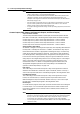
Method of Detecting Contact Inputs
The above operations are carried out on the rising or falling edge of the contact signal
(edge) or the ON signal lasting at least 250 ms (trigger). The remote signal rises when
the contact switches from “open to closed” and falls when the contact switches from
“closed to open.” For open collector signals, the remote signal rises when the collector
signal (voltage level of the input terminal) goes from “high to low” and falls when the
collector signal goes “low to high.”
Rising and falling edges
Trigger
Rising
Falling
250 ms or more
1.5 Contact Input/Output Related Settings