
Owner's manual


2-23
IM 04L31A01-01E
Installation and Wiring
3
2
1
4
5
6
7
8
9
10
11
12
13
14
2.6 Transmitter Power Supply Wiring (/TPS4
Option)
NING WARNING
• To prevent the possibility of electric shock when wiring, confirm that the power
supply source is turned OFF.
CAUTION
• Do not short the transmitter power supply output terminal or apply external
voltage to it. This may cause damage to the CX2000.
• Do not use current that exceeds the maximum output current (25 mADC). This
may cause damage to the CX2000.
• To prevent fire, use signal wires having a temperature rating of 70°C or more.
Output Specifications
Number of loops: 4
Output voltage: 22.8 to 25.2 V (under rated load current)
Rated output current: 4 to 20 mADC
Maximum output current: 25 mADC (overcurrent protection operation current: approx.
68 mADC)
Maximum length of cable: 2 km (when using the CEV cable)
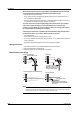
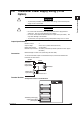
Connection
To use the transmitter output as a measurement input, connect the CX2000 and
transmitter as shown below.
–
+
+
–
Transmitter
Current
CX2000
Transmitter
power supply
output terminal
Measurement
input terminal
Shunt resistor: 250 Ω
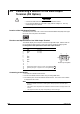
Terminal Position
Arrangement Position of Terminal Block
Transmitter power supply
output terminal block
(/TPS4 option)