
Owner's manual


2-15
IM 04L31A01-01E
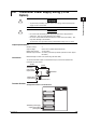
Installation and Wiring
3
2
1
4
5
6
7
8
9
10
11
12
13
14
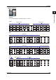
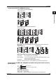
Option Terminal
VIDEO OUT(VGA)
L
N
Symbols
NO: Normally opened, NC: Normally closed, C: Common
/CST1
Contact inputTransistor output
625
626
627
628
629
630
622
623
619
620
613
614
615
610
611
612
607
608
609
604
605
606
4
5
6
7
8
9
10
11
12
C
C
C
1
2
2
4
5
6
C
7
8
C
628
629
630
9
10
C
628
629
630
11
12
C
1
2
3
601
602
603
/A6
Alarm output
625
626
627
628
629
630
619
620
610
611
612
NC
C
NO
NC
C
NC
C
NO
621
NO
NC
C
NO
616
617
618
NC
C
NO
06 05 04 03 02 01
634
635
636
NC
C
NO
/A6R
Measurement remote inputAlarm output
625
626
627
628
629
630
619
620
610
611
612
607
608
609
604
605
606
3
4
5
6
7
8
NC
C
NO
NC
C
NC
C
NO
621
NO
NC
C
NO
616
617
618
NC
C
NO
06 05 04 03 02 01
634
635
636
NC
C
NO
C
1
2
601
602
603
/A4F
FAIL output Memory end output Alarm output
625
626
627
628
629
630
619
620
610
611
612
NC
C
NO
NC
C
NC
C
NO
621
NO
NC
C
NO
616
617
618
NC
C
NO
04 03 02 01
634
635
636
NC
C
NO
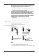
2.3 Wiring