
Owner's manual


2-10 IM 04L31A01-01E
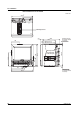
Control Input Terminal (6 loops)
VIDEO OUT(VGA)
L N
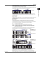
Chracters indicating the type of input/output signal
Terminal number
005
A
+
One screw terminal is shown in the figure below.
The upper and lower symbols represent a unique terminal number and the terminal type, respectively.
No screw terminal is attached.
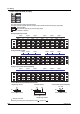
During Single-Loop Control
LOOP1
PV(RSP)
LOOP2
PV(RSP)
LOOP3
PV(RSP)
LOOP4
PV(RSP)
LOOP5
PV
LOOP6
PV
028
029
030
b
A
+
B
−
031
032
033
b
A
+
B
−
025
026
027
b
A
+
B
−
022
023
024
b
A
+
B
−
019
020
021
b
A
+
B
−
016
017
018
b
A
+
B
−
013
014
015
b
A
+
B
−
010
011
012
b
A
+
B
−
007
008
009
b
A
+
B
−
004
005
006
b
A
+
B
−
During Cascade Control
LOOP1
PV(RSP)
LOOP3
PV(RSP)PV
LOOP5
PV
LOOP2
PV
LOOP6
LOOP4
PV
028
029
030
b
A
+
B
−
031
032
033
b
A
+
B
−
025
026
027
b
A
+
B
−
022
023
024
b
A
+
B
−
019
020
021
b
A
+
B
−
016
017
018
b
A
+
B
−
013
014
015
b
A
+
B
−
010
011
012
b
A
+
B
−
007
008
009
b
A
+
B
−
004
005
006
b
A
+
B
−
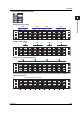
During Loop Control with PV Switching
LOOP1
PV1PV2
LOOP2
PV1PV2
LOOP3
PV1PV2
LOOP4
PV1PV2
LOOP5
PV
LOOP6
PV
028
029
030
b
A
+
B
−
031
032
033
b
A
+
B
−
025
026
027
b
A
+
B
−
022
023
024
b
A
+
B
−
019
020
021
b
A
+
B
−
016
017
018
b
A
+
B
−
013
014
015
b
A
+
B
−
010
011
012
b
A
+
B
−
007
008
009
b
A
+
B
−
004
005
006
b
A
+
B
−
Control Modes and Input/Output Connections
SP
PV
PV
Loop2
Control output terminal
Loop1
RSP
SP
Loop1SP
PV1
PV2
Control output terminal
Loop1SP
PV
Control output terminal
Single-loop control
Cascade control
Loop control with PV switching
When using remote input as target setpoints, replaces .
: Indicates a terminal.
Single-loop control
2.3 Wiring