
Owner's manual


2-5
IM 04L31A01-01E
Installation and Wiring
3
2
1
4
5
6
7
8
9
10
11
12
13
14
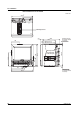
2.3 Wiring
Arrangement of the Input/Output Terminals
If you specify a model with 6 internal control loops and 20 measurement channels
(CX2620) and option terminals, seven terminal blocks are arranged on the rear panel of
the CX2000 as shown in the following figure. The option terminal block, which can be /
A6 [measurement alarm (6 DOs)], /A6R [measurement alarm (8 DIs, 6 DOs)], /A4F
[measurement alarm (4 DOs, with FAIL/memory end output relay)], /A4FR [measurement
alarm (8 DIs, 4 DOs, with FAIL/memory end output relay)], /CST1 [control DIO expansion
(12 DIs, 12 DOs)], or /TPS4 [24 VDC transmitter output (4 loops)], is installed at the
lower left section. If several terminal blocks are not installed according to the
specification made at the time of purchase, protection covers are attached in place of the
corresponding terminal blocks.
VIDEO OUT(VGA)
L N
Analog control input
terminal block
(10 inputs)
Measurement input
terminal block
(CH1 to CH10)
Measurement input
terminal block
(CH11 to CH20)
Loop 1 and 2 control
output terminal block
Loop 3 and 4 control
output terminal block
Loop 5 and 6 control
output terminal block
Option terminal block
(Options /A6, /A6R,
/A4F, /A4FR, /CST1,
and /TPS4)
Note
• The installation position of each terminal block is fixed and cannot be changed.
• For a description on the connection of communication interfaces such as the serial or Ethernet
interface, see the
DAQSTATION CX1000/CX2000 Communication Interface User’s Manual)
.
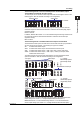
Input/Output Assignments of the Analog Control Input Terminal Block
There are 10 input terminals. When PV/SP computation is OFF, the PV inputs (PV) and
RSP inputs (RSP) are assigned as shown in the following figure depending on the
number of loops used and the control mode. The following figure denotes the three
terminals (/b, +/A, -/B) of a single column using a single cell. In addition, of the 12
columns of terminals, the columns at each end that have no terminal screws because
they are not used are omitted.
LOOP1
21
PV
(RSP)
(RSP)
PV
PV1PV2
LOOP2 LOOP5
LOOP6
21
PV
1
PV
1
PV
(RSP)
PV
PV1PV2
LOOP3
21
PV
(RSP)
(RSP)
PV
PV1PV2
LOOP4
21
PV
(RSP)
PV
PV1PV2
• 6 loops
PV, PV1, PV2: PV input, (RSP): RSP input
(not used during program control), : unused terminal
During single-loop control
During cascade control
During loop control with
PV switching
[Control mode setting]
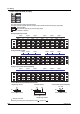
LOOP4 LOOP3 LOOP2 LOOP1
21321 32121
PVPV
(RSP)(RSP)
(RSP)
(RSP)
PVPV
PV1PV1 PV2PV2
PVPV
(RSP)(RSP)
(RSP)
(RSP)
PVPV
PV1PV1 PV2
PV2
• 4 loops
PV, PV1, PV2: PV input, (RSP): RSP input
(not used during program control), : unused terminal
During single-loop control
During cascade control
During loop control with
PV switching
[Control mode setting]